FSC-BT986 Programming User Guide
Introduction
Description
This instruction manual is provided for engineers to develop FSC-BT986 series Bluetooth modules, which are also suitable for BT982 and BT981 series modules
Module default configuration
Name |
FSC-BT986 |
LE-Name |
FSC-BT986-LE |
Pin Code |
0000 |
Secure Simple Pairing Mode |
On |
Service UUID |
FFF0 |
Write UUID |
FFF2 |
Notify UUID |
FFF1 |
UART Baudrate |
115200/8/N/1 |
Hardware Interface
Application Schematic
FSC-BT986 for example:
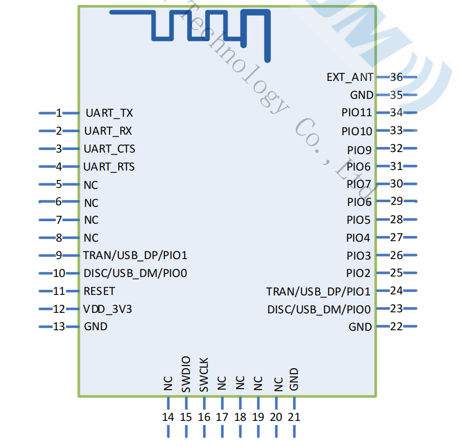
PIN Definition Descriptions
Pin |
Pin Name |
Type |
Pin Descriptions |
|---|---|---|---|
1 |
UART_TX |
O |
Serial Transmitter Data |
2 |
UART_RX |
I |
Serial Receiver Data |
3 |
UART_CTS |
I/O |
UART Clear to Send(no connection request) |
4 |
UART_RTS |
I/O |
UART Request to Send(no connection request) |
24 |
Tran/USB_DP/PIO1 |
I/O |
UART mode control pin, H=command mode ,L=throughput mode |
23 |
Disc/USB_DM/PIO0 |
I/O |
Disconnect the connecting pin |
11 |
RESET |
I |
Active-low reset input |
12 |
VDD |
Power |
Power supply voltage 3.3V, LDO power supply preferred |
13 |
GND |
GND |
GND |
15 |
ICE |
I/O |
Writing firmware pin |
32 |
LED |
O |
Bluetooth not connected to output square wave, Bluetooth connected to output high level |
33 |
STATUS |
O |
Connection state, output. H=Connected , L=No connection |
36 |
EXT_ANT |
ANT |
Changing the 0 ohm resistance near the antenna, it is possible to connect a Bluetooth antenna externally |
Note
To use the 23 and 24 pin control modules AT+PIOCFG command is required to enable the function
Physical Interface
The module only needs to be connected to VDD/GND/UART_RX/UART_TX ready to use.
If the MCU needs to obtain the connection status of the Bluetooth module, it needs to be connected to the STATUS pin.
After drawing the schematic diagram, please send it to Feasycom for review to avoid Bluetooth distance not achieving the best effect.
Function Description
GPIO Indications
Connection status PIN 24
State |
Description |
|---|---|
Low level |
Throughput mode |
High level |
AT command mode |
Connection status PIN 23
State |
Description |
|---|---|
Low level |
/ |
High level |
disconnected |
LED PIN 32
State |
Description |
|---|---|
1Hz square wave |
disconnected |
High level |
connected |
Connection status PIN 33
State |
Description |
|---|---|
Low level |
disconnected |
High level |
connected |
Working mode
Throughput mode |
Bluetooth is not connected, and the data received by the serial port is parsed according to AT instructions;
After Bluetooth connection, all data received from the serial port is sent to the remote Bluetooth as is.
|
AT command mode |
Bluetooth is not connected, and the data received by the serial port is parsed according to AT instructions; After Bluetooth connection,
the data received by the serial port is still parsed according to the AT command. When sending data to the remote end, send the AT+SPPSEND command.
|
GATT Throughput Service
Type |
UUID |
Service |
Description |
Service |
0xFFF0 |
Transparent transmission service |
|
Write |
0xFFF2 |
Write,Write Without Response |
APP sent to module |
Notify |
0xFFF1 |
Notify |
Module sent to APP |
AT Command Description
Specification Description
Applicable to the entire document
{} : Including content in {…} is optional
<< : COMMAND sent by the host to the module
>> : Module responds to the host’s**RESPONSE**
Command
Command Format
All instructions start with**AT**,and end with**<CR><LF>**
<CR> represents carriage return, corresponding to HEX as 0x0D
<LF> represents a line break, corresponding to HEX as 0x0A
If the instruction contains parameters, the parameters should be separated by**=**
If the instruction contains multiple parameters, the parameters should be separated by**,**
If the instruction returns a response, the response starts with <CR><LF>, ends with**<CR><LF>**
The module should always return the result of instruction execution (success returns OK,failure returns ERROR)
Indication
Indication
All notifications start with<CR><LF>,and end with<CR><LF>
If the notification contains parameters, the parameters should be placed after ‘=’
If the notification contains multiple parameters, the parameters should be separated by ‘,’
Command Table
General Commands
AT+HELP - Query firmware functions and command
Command |
AT+HELP |
Response |
<MODULE DEFAULT PARAMETER>
<COMMAND SUMMARY: DESCRIPTION: PROFILE CATEGORY>
|
Description |
Using the help command to obtain basic summary information |
Note
If you need to upgrade to the latest version, please refer t OTA instructions
AT - UART Communication Test
Command |
AT |
Response |
OK |
Description |
Test the UART communication between HOST and Module after power on, baudrate changed, etc. |
AT+REBOOT - Soft Reboot
Command |
AT+REBOOT |
Response |
OK |
Description |
Module release all Bluetooth connections with remote device then reboot. |
AT+RESTORE - Restore Factory Settings
Command |
AT+RESTORE |
Response |
OK |
Description |
Module restore all factory settings then reboot. |
AT+BTEN - Disable/Enable Module
Command |
AT+BTEN{=Param1} |
|
Disable/Enable Module(0/1,default:0)
0: Bluetooth disable
1: Bluetooth enable
|
Response |
+BTEN=Param |
Description |
Disable/Enable Module |
AT+NAME - Read/Write BR/EDR Local Name
Command |
AT+NAME{=Param1{,Param2}} |
|
BR/EDR Local Name(1~31 Bytes ASCII) |
|
Enable MAC address suffix (0~2,default:0)
0: Disable suffix
1: Enable suffix“-XXXX”(lower 4 bytes of MAC address)
2: Enable suffix“-XXXX”(lower 6 bytes of MAC address)
|
Response |
+NAME=Param |
|
BR/EDR local name |
Description |
Write local name if parameter existence, otherwise read current local name |
AT+LENAME - Read/Write BLE Local Name
Command |
AT+LENAME{=Param1{,Param2}} |
|
BLE local name(1~31 Bytes ASCII) |
|
MAC address suffix(0~2,default:0)
0: Disable suffix
1: Disable suffix“-XXXX”(lower 4 bytes of MAC address after local name)
2: Enable suffix“-XXXX”(lower 6 bytes of MAC address after local name)
|
Response |
+LENAME=Param |
|
BLE local name |
Description |
Write local BLE local namename if parameter existence, otherwise read current local name |
AT+PIN - Read/Write Pin Code
Command |
AT+PIN{=Param} |
|
Pin code(4~15 Bytes ASCII, default:0000) |
Response |
+PIN=Param |
Description |
When+SSP=0, the pairing password is valid |
AT+PLIST - Read/Clear Paired Record
Command |
AT+PLIST{=Param} |
|
(0 / 1~8)
(0) Clear all paired record
(1~8) Clear specific paired record with index
|
Response1 |
+PLIST=Param1, Param2 |
|
(1~8) Paired device’s index |
|
(MAC) Paired device’s MAC address |
Response2 |
+PLIST= Pairing record query completed |
AT+BAUD - Read/Write UART Baudrate
Command |
AT+BAUD{=Param} |
|
Baudrate(4800/9600/19200/38400/57600/115200/
230400/460800/921600,256000,512000,1000000, default:115200)
|
Response |
+BAUD=Param |
|
Baudrate |
Description |
Module’s baudrate will be changed immediately after received this command |
AT+LPM - Turn On/Off Low Power Mode
Command |
AT+LPM{=Param} |
|
Low Power Mode (0/1, default: 0)
0: Turn Off
1: Turn On
|
Response |
+LPM=Param |
|
Low Power Mode |
Description |
Read and configure Low Power Mode |
AT+VER - Read Firmware Version
Command |
AT+VER |
Response |
+VER=Param |
|
Firmware version |
Description |
Read module’s firmware version |
AT+ADDR - Read BR/EDR MAC Address
Command |
AT+ADDR |
Response |
+ADDR=Param |
|
Module’s BR/EDR MAC address(12 Bytes ASCII) |
AT+LEADDR - Read BLE MAC Address
Command |
AT+LEADDR |
Response |
+LEADDR=Param |
|
Module’s BLE MAC address(12 Bytes ASCII) |
AT+COD: Read/Write Class Of Device
Command |
AT+COD=Param |
|
Class of device(6 bytes ASCII, default:240404 Handsfree device) |
Response |
+COD=Param |
Related configurations refer to COD.
AT+TPMODE - Turn On/Off Throughput Mode
Command |
AT+TPMODE{=Param} |
|
Mode(0~1,default: 0) 0: AT command mode 1: Throughput mode |
Response |
+TPMODE=Param |
Description |
When SPP/HID/GATT profile connected and throughput mode is on, the AT command will be de-active,
every byte received via physical UART will be sent to air, vice visa.
|
AT+FLOWCTL - Turn On/Off Hardware Flow Control
Command |
AT+FLOWCTL{=Param1} |
|
Option(0~1,default0) 0: Turn Off 1: Turn On |
Response |
+FLOWCTL=Param |
Description |
Turn On/Off Hardware Flow Control |
AT+SSP - Turn On/Off Secure Simple Pairing
Command |
AT+SSP{=Param} |
|
PROFILE mode (0~1, default:0) 0: Turn off SSP 1: Turn on SSP
|
Response |
+SSP=Param |
Note |
Pin code input will be bypassed if simple pairing is on in pairing procedure<need reboot> |
AT+MODE - Read/Write Bluetooth Mode
Command |
AT+MODE{=Param} |
|
Pairing mode (0~4, default:0)
(0) NONE PROFILE
(1) SPP PROFILE
(2) HID PROFILE
(3) BLE PROFILE
(4) ALL PROFILE
|
Response |
+SSP=Param |
AT+AUTOCONN - Turn On/Off Power On Auto Reconnect<need reboot>
Command |
AT+AUTOCONN{=Param} |
|
0: Turn off
1: Turn on
|
Response |
+AUTOCONN=Param |
Description |
Module will attempt to connect last device after power on if set |
AT+PIOCFG - PIO Function Configuration
Command |
AT+PIOCFG{=Param,Param1} |
|
0: Disable Command/Transmission mode switch function
1: Enable Command/Transmission mode switch function
|
|
0: Disable Bluetooth disconnect function
1: Enable Bluetooth disconnect function
|
Response |
+PIOCFG=Param |
Description |
AT+DSCA - Release All Connections
Command |
AT+DSCA |
Description |
Module release all Bluetooth connections with remote device |
AT+SCAN - Scan Nearby Devices
Command |
AT+SCAN=Param1{,Param2{,Param3}} |
|
Scan type(0~2)
0: Stop scan
1: Scan nearby BR/EDR devices
2: Scan nearby BLE devices(some firmware do not support)
3: Scan nearby BR/EDR/BLE devices(some firmware do not support)
|
|
(1~48)Scan period. unit:1.28s, default:12.8s |
|
(1~25 Bytes ASCII)Scan period. |
Description |
Format description refer to: +SCAN - Scan Result |
AT+SECURITY - Turn on/off security verification
Command |
AT+SECURITY{=Param1} |
|
mode(0~1,default:0) 0: turn off 1: turn on |
Response |
+SECURITY=Param |
Description |
Turn on/off security verification |
AT+TXPOWER - Read/Write TX power
Command |
AT+TXPOWER{=Param} |
|
TX power(0~2) | 0: 0db | 1: 3db | 2: 5db |
Response |
+TXPOWER=Param |
|
TX power |
Description |
Read/Write TX power |
AT+UARTCFG - Read/Write Serial Port Configuration
Command |
AT+UARTCFG{=Param} |
|
mode (0~5)
bit0:
0 - 1-bit stop bit
1 - 2-bit stop bit
bit2~bit1:
00 - None
01 - Odd
10 - Even
|
Response |
+UARTCFG=Param |
|
Mode (0~5) |
Description |
Modifying Serial Port Configuration(Stop bit and check bit) |
AT+LINKCFG - Automatic Search Link Configuration
Command |
AT+LINKCFG{=Param} |
|
mode (0~2)
0:Turn off automatic search link
1:Turn on SPP automatic search link
2:Turn on BLE automatic search link
|
Description |
If this command is configured, the module will automatically search for links based on the configuration |
AT+RSSICFG - Read/Write RSSI Configuration
Command |
AT+RSSICFG{=Param,Param1} |
|
High RSSI signal strength |
|
Low RSSI signal strength |
Description |
PIN34 pin pulled low when signal strength is greater than
ParamPIN34 pin pulled up when signal strength is less than
Param1PIN34 level remains unchanged when the signal strength is between
Param``~ ``Param1 |
Bluetooth Serial Commands (BR/EDR SPP)
AT+SPPSTAT - Read SPP State
Command |
AT+SPPSTAT |
Response |
+SPPATAT=Param |
Description |
Format description refer to:ref:REF107 |
AT+SPPCFG - Read/Write SPP Configuration
Command |
AT+SPPCFG{=Param} |
|
mode(0,1)
0:Turn off spp dynamic registration
0:Turn on spp dynamic registration
|
Response |
+SPPCFG=Param |
Description |
After enabling dynamic registration, the module will register the SPP service
when connecting,unregister SPP service when disconnected
|
AT+SPPCONN - Establish SPP Connection
Command |
AT+SPPCONN{=Param} |
|
MAC address of target device(12 Bytes ASCII) |
AT+SPPDISC - Release SPP Connection
Command |
AT+SPPDISC |
Description |
Release current SPP connection with remote device |
AT+SPPSEND - Send Data Via SPP
Command |
AT+SPPSEND=Param1,Param2 |
|
Payload length (1~236) |
|
Payload (1~236 Bytes UTF8) |
Description |
If throughput mode is on, this command is de-active |
Bluetooth Serial Commands (LE Peripheral)
AT+GATTSTAT - Read LE Peripheral State
Command |
AT+GATTSTAT |
Response |
+GATTATAT=Param |
Description |
Format description refer to: +GATTSTAT - LE Peripheral State (as slave module) |
AT+ADVADDR - Turn on/off broadcast address
Command |
AT+ADVADDR{=ram} |
|
mode(0~1,default:1) 0: turn off broadcast address 1: turn on broadcast address |
Response |
+ADVADDR=Param |
Description |
Turn on/off broadcast address |
AT+IBEACON - Turn on/off ibeacon broadcast
Command |
AT+IBEACON{=Param} |
|
mode(0~1,default:0) 0: Turn off ibeacon broadcast 1:Turn on ibeacon broadcast |
Response |
+IBEACON=Param |
Description |
Turn on/off ibeacon broadcast |
AT+ADVDATA - Read/Write BLE Broadcast 0xFF Data
Command |
AT+ADVDATA{=Param} |
|
Manufacturer defined broadcast data (data length not exceeding 27) |
Response |
+ADVDATA=Param |
|
Tag is broadcast data of 0xFF |
Description |
The manufacturer’s custom broadcast data tag is 0xFF |
AT+ADBLE - Turn on/off AndroidBLE
Command |
AT+IBEACON{=Param} |
|
mode(0~1,default:1) 0: turn off AndroidBLE 1: turn on AndroidBLE |
Response |
+IBEACON=Param |
Description |
After turning on, the SPP and BLE addresses will be two different addresses | when turning off, the SPP and BLE addresses will be the same address |
AT+UUIDCFG - Read/Write UUID
Command |
AT+UUIDCFG{=Param1,Param2,Param3} |
|
service UUID (defalut: 0000) |
|
write UUID (defalut: 0000) |
|
notify UUID (defalut: 0000) |
Response |
+UUIDCFG=Param1,Param2,Param3 |
Description |
Customized data transfer reset UUID, supporting 32/128 bit UUID By default: | service UUID = 0xFFF0 | write UUID = 0XFFF2 | notify UUID = 0XFFF1 |
AT+GATTSEND - Send Data Via LE Peripheral
Command |
AT+GATTSEND=Param1,Param2 |
|
Payload length (1~236) |
|
Payload (1~236 Bytes UTF8) |
Description |
If throughput mode is on, this command is de-active |
AT+LESTAT - Read LE Central State
Command |
AT+LESTAT |
Response |
+LEATAT=Param |
Description |
Format description refer to: +LESTAT - LE Central State (as master module) |
AT+LECCONN - Establish LE Central Connection
Command |
AT+LECCONN{=Param1{,Param2{,Param3{,Param4}}}} |
|
MAC address of target device (12 Bytes ASCII) + MAC address type (1 Bytes ASCII) |
|
Service UUID |
|
Write UUID |
|
Notify UUID |
Response |
OK |
Description |
Initiate a connection to the specified device, with parameters consisting of target device (12 Bytes ASCII) + MAC address type
(1 Bytes ASCII) composition, usually the address type is “0” or “1”.
Type acquisition method:
Scan the second parameter returned using AT+SCAN, for example:
+SCAN=0,0,DC0D30001ED4,-65,10,FSC-BT946
Establish LE Central Connection AT command
AT+LECCONN=DC0D30001ED40
|
AT+LESEND - Send Data Via LE Central
Command |
AT+LESEND=Param1,Param2 |
|
Data length |
|
Data |
Response |
OK |
Description |
If throughput mode is on, this command is de-active |
Bluetooth Serial Commands (HID)
AT+HIDSTAT - Read HID State
Command |
AT+HIDSTAT |
Response |
+HIDATAT=Param |
Description |
Format description refer to: +HIDSTAT - HID State |
AT+HIDCONN - Establish HID Connection
Command |
AT+HIDCONN{=Param} |
|
MAC address of target device(12 Bytes ASCII) |
AT+HIDDISC - Release HID Connection
Command |
AT+HIDDISC |
Description |
Release current HID connection with remote device |
AT+HIDOSK - IOS Device Eject Keyboard Toggle
Command |
AT+HIDOSK |
Description |
This instruction applies only to the IOS Device |
AT+HIDMODE - Read/Write HID Transfer Mode
Command |
AT+HIDMODE{=Param} |
|
HID mode(0~1), default:1
(0) Hex key code
(1) Ascii key code (English)
|
Note |
The module can support various keyboard languages through specific firmware, such as:
TURKEY SPAIN PORTUGAL FRANCE GERMANY ITALY CZECH JAPAN
|
AT+HIDDLY - Read/Write HID Send Delay
Command |
AT+HIDDLY{=Param} |
|
HID report period in millisecond, default 10 ms |
AT+HIDSEND - Send Data Via HID
Command |
AT+HIDSEND=Param1,Param2 |
|
Report length |
|
Report payload |
Note |
For special key code:
0x0D -> ENTER
0x08 -> BACKSPACE
0x09 -> TAB
0x20 -> SPACE
|
Description |
If throughput mode is on, this command is de-active |
Bluetooth Serial Indications
+SPPSTAT - SPP State
Format |
+SPPSTAT=Param |
|
(0) Unsupported
(1) Standby
(2) Connecting
(3) Connected
|
+SCAN - Scan Result
Format1 |
+SCAN={ : start scanning |
Format2 |
+SCAN =Param1,Param2,Param3, Param4,Param5,Param6 |
|
Index |
|
Device address type(1 Bytes ASCII) |
|
MAC address (12 Bytes ASCII) |
|
RSSI |
|
Size of Param6 if exist |
|
Device Name |
Format3 |
+SCAN=} : cease scanning |
+GATTSTAT - LE Peripheral State (as slave module)
Indication |
+GATTSTAT=Param |
|
(0) Unsupported
(1) Standby
(2) Connecting
(3) Connected
|
Description |
In instruction mode, when connection status of the module changes,module will actively report it through +GATTSTAT |
+LESTAT - LE Central State (as master module)
Indication |
+LESTAT=Param |
|
(0) Unsupported
(1) Standby
(2) Connecting
(3) Connected
|
Description |
In instruction mode, when connection status of the module changes,module will actively report it through +LESTAT |
+HIDSTAT - HID State
Format |
+HIDSTAT=Param |
|
(0) Unsupported
(1) Standby
(2) Connecting
(3) Connected
|
+DATA - Received Bluetooth data report
Indication |
+DATA=Param1,Param2,Param3 |
|
Index |
|
Data length |
|
Data |
Description |
Throughput mode:Report data without +DATA prefix +DATA=12345
AT command mode:Report data without+DATA prefix +DATA=1,5,12345
|
Application Scenario
Read/Write Module Default Parameters
When the module is not connected to Bluetooth, it will parse the serial port data according to AT command. The host can query and modify the default parameters of the module, as shown in the following figure:
Change the device name to ABC
Query device name
Query Bluetooth address
The process of sending data
The module will continuously send broadcast data to the outside when powered on, and the remote Bluetooth (mobile phone) can obtain the broadcast packet through search and initiate a connection request to the module. After successful connection, the module will pull up the connection status pin to notify the host that the Bluetooth connection is successful. The host can send data to the remote Bluetooth through the Bluetooth module, and the remote Bluetooth can also send data to the host.
The module used as a master module to connect to remote devices
The module can serve as the master module to connect to the slave module and the master module can send instructions to control the module for scanning, connecting, and disconnecting. The following figure shows the process of connecting to other devices:
FAQ
How can IOS phones obtain Bluetooth MAC addresses?
For security reasons, the IOS system converts the Bluetooth MAC address into UUID at the bottom layer
and sends it to the upper layer application. So the app cannot obtain the MAC address of the device.
FSC-BT986 will place the MAC address in the broadcast by default, and the APP can obtain the MAC address from the broadcast packet using the following method.
- (void)centralManager:(CBCentralManager *)central didDiscoverPeripheral:(CBPeripheral *)peripheral advertisementData:(NSDictionary *)advertisementData RSSI:(NSNumber *)RSSI
{
    if(![self describeDictonary:advertisementData])
    {
        NSLog(@"is not fsc module");
        return;
    }
}

- (Boolean)describeDictonary: (NSDictionary *) dict
{
    NSArray *keys;
    id key;
    keys = [dict allKeys];
    for(int i = 0; i < [keys count]; i++)
    {
        key = [keys objectAtIndex:i];
        if([key isEqualToString:@"kCBAdvDataManufacturerData"])
        {
            NSData *tempValue = [dict objectForKey:key];
            const Byte *tempByte = [tempValue bytes];
            if([tempValue length] == 6)
            {
                // tempByte MAC address
                return true
            }
        }else if([key isEqualToString:@"kCBAdvDataLocalName"])
        {
            //there is name
            //NSString *szName = [dict objectForKey: key];
        }
    }
    return false;
}