FSC-DB200 Development Board User Guide
Introduction
Overview
Features
Application Module
Hardware and Function
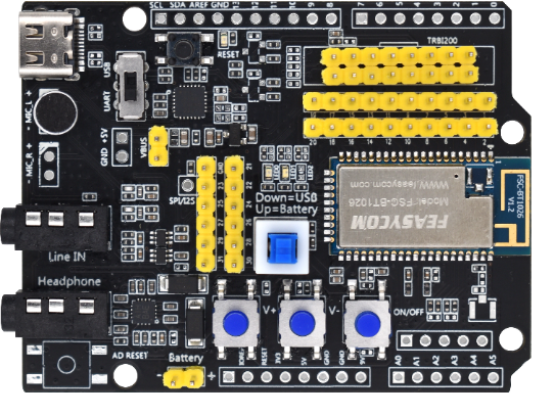
Sample Image
Funticon Design
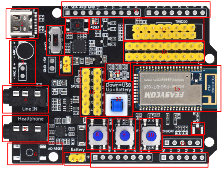
Function Description
NO. |
Description |
remark |
|---|---|---|
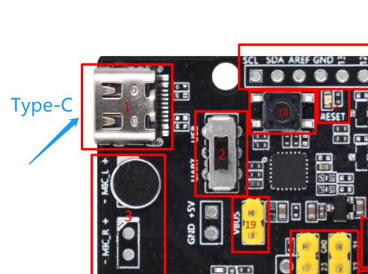
1 * |
Type-C |
Power the module/communicate with the module/charge the battery through the module |
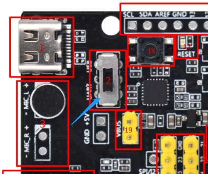
2 |
USB/UARTswitch |
The UART can be selected to communicate with the module, and the USB function of the module can be selected;
Not all modules have USB capability
|
3 |
microphone |
HFP (for outgoing calls, the default channel is L);
And applications that require microphones
|
4 |
Audio input |
Standard 3.5mm audio socket |
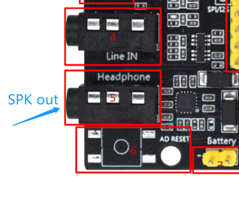
5 |
Audio output |
Standard 3.5mm headphone output drives 16/32 ohm speakers up to 60mW |
6 |
Adu board reset button |
Reset the extended adu board. The default is empty |
7 |
Battery powered |
Lithium battery interface. 3.7V to 4.2V. Do not exceed the voltage, otherwise the module will be damaged |
8 |
Volume plus |
Short press Volume increase/Long press next track |
9 |
Volume down |
Short press volume decrease/Long press previous track |
10 |
On-off key |
Long press 2s switch machine;
Play music: short press pause/play;
Incoming call: Press to answer and then press to hang up
|
11 |
Adu board expansion row pin |
Adu board extension, empty by default |
12 |
Adu board indicator light |
Adu board status indication |
13 |
Analog audio differential output pin |
Expansion pin, empty by default |
14 |
External IPEX seat son |
The module external antenna is connected to the seat |
15 |
module |
Can support BT1026X series/BT1035 / BT1036C/BT1032C BT955 / BT958 and so on |
16 |
Module pin |
Module each pin |
17 |
TRBI200 |
TRBI200 burner interface, empty by default |
18 |
Module reset key |
Press the module to reset |
19 * |
Battery charging/module upgrade |
Battery charging in short circuit state, module upgrade/fixed frequency |
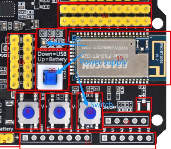
20 * |
Module power supply |
Short circuit: Type-C supplies power to the module;
Off: The battery supplies power to the module,
Or charge the battery when the Type-C has input voltage and the “Battery charge/Module upgrade pin” is short circuited
|
22 |
Module indicator |
The blue light flashes quickly for pairing, and the long light indicates that it is connected. If the green light is steady on, the SPP/BLE connection is successful |
Note
The three marked with * can be combined to achieve battery charging, and the maximum current is 200mA. Generally, this function is disabled by default. Not all modules support battery charging.
Development and Use
Driver
Tools
Quick Start
Take FSC-BT1026C dual-mode Bluetooth audio module and universal firmware as an example to demonstrate the quick operation steps:
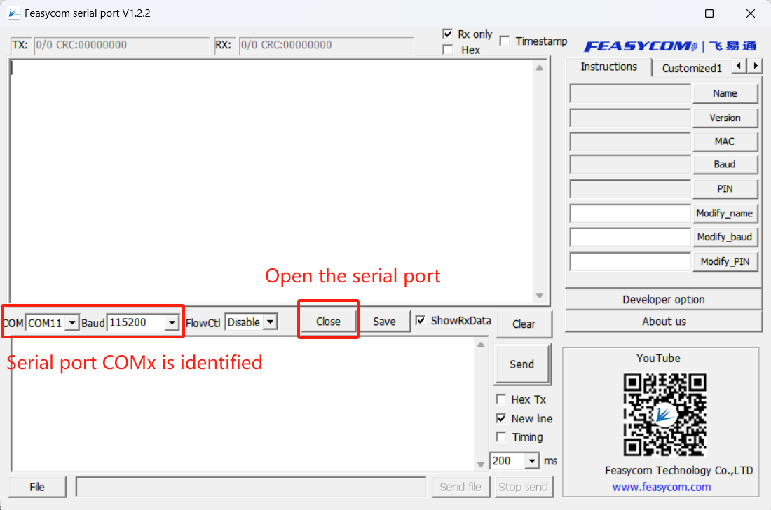
(1). Switch the development board to UART serial communication debugging mode:
(2). Connect the development board to the PC through a Type-C cable
(3). After the connection, the PC recognizes the serial port COMx
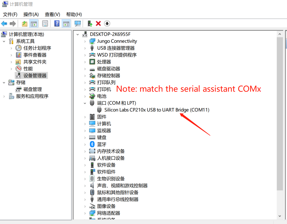
Feasycom serial debugging assistant Serial identification:
(4). The module is powered on
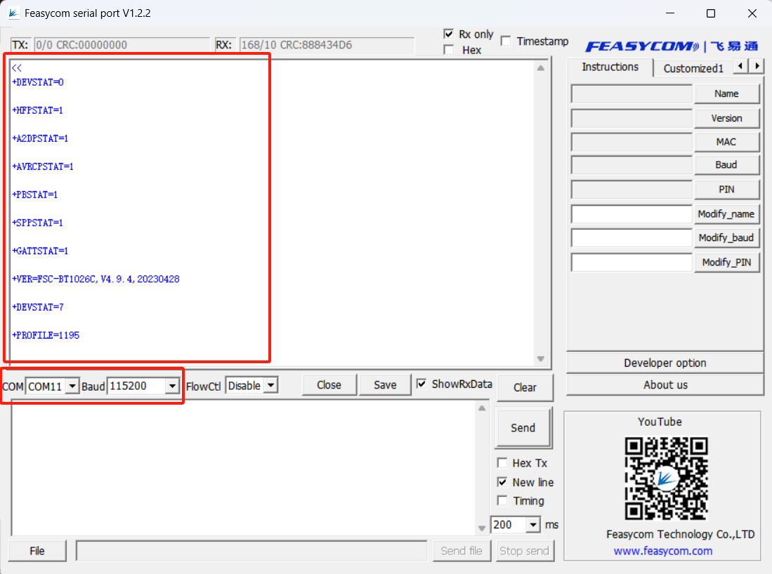
This demonstration, firmware configuration, power-on response configuration data, different firmware may be different, the actual situation shall prevail.
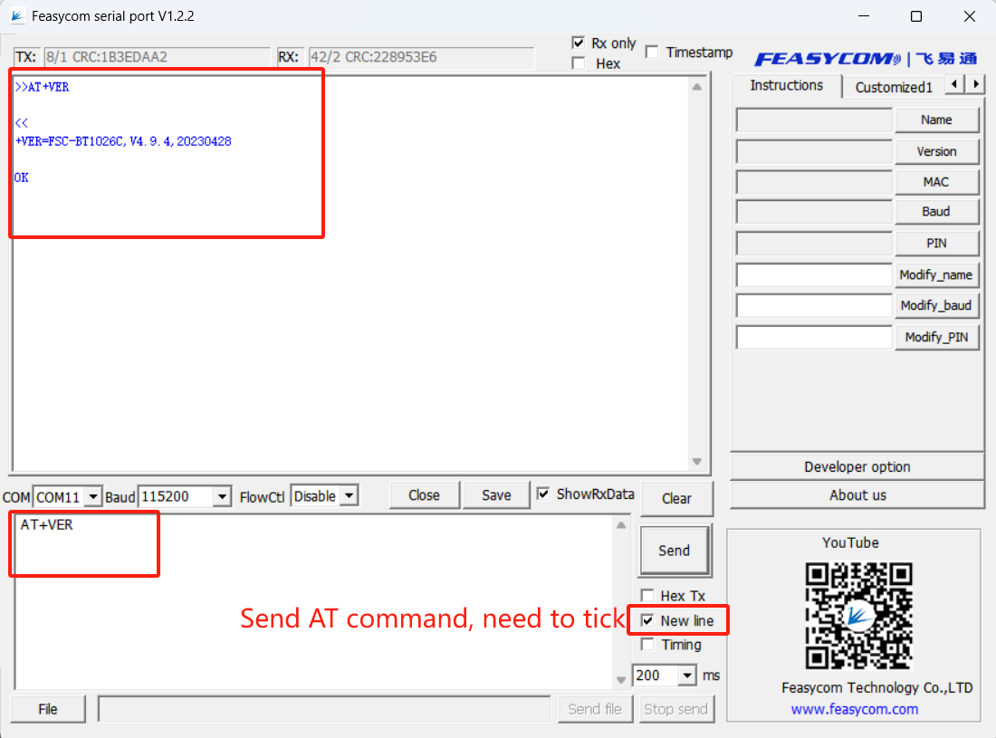
Supports the use of modules with AT commands, such as sending AT+VER in response to the firmware version information of the module
(4). Connect the speaker or headphones to the SPK audio output port (component number 5) of the development board through the 3.5mm AUX audio cable.
(5). Scan and connect modules on the mobile phone
(6). Music mode(A2DP)
(7). Call mode (HFP)
AT Communication Example