Feasycom Bluetooth AoA Demo Kit and RTLS Deployment Guide
Introduction
AOA Demo Kit | Bluetooth Angle of Arrival (AoA) DEMO Kit for Real-Time Locating System (RTLS)
Feasycom AOA Demo kit is a high accuracy RTLS (Real-Time Locating System) Evaluation kit based on Bluetooth AOA technology. It contains 1 AoA gateway and 6 tags. The gateway supports POE/DC power supply, making it easy to deploy and test. The purpose of Demo kit is to help customers quickly complete prototype verification and accelerate project implementation progress.
Feasycom AoA Demo Kit
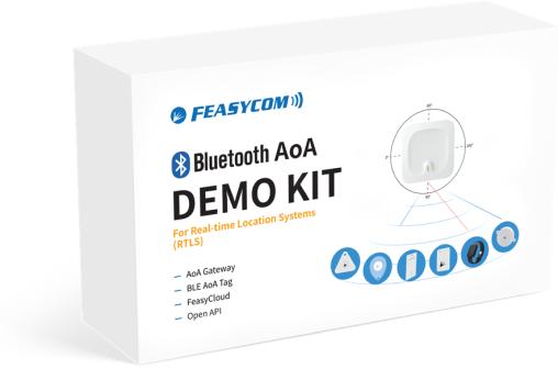
DEMO Kit Includes:
Bluetooth AoA Gateway: |
FSC-BP203 |
Bluetooth Version : |
Bluetooth Low Energy (BLE) 5.4 |
Installation Method : |
Ceiling/side-hanging |
Power Supply : |
POE/DC |
Maximum Installation Height: |
10m |
Coverage : |
The coverage radius is 2 times of the installation height |
Accuracy : |
0.1~1m |
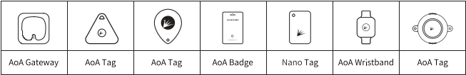
Bluetooth AoA Tags: |
FSC-BP10x Series |
Bluetooth Version : |
Bluetooth Low Energy (BLE) 5.1/5.4 |
Key : |
Could be SOS |
Gravity Sensor : |
YES |
LED Light : |
YES |
Customizable : |
YES |
Configurable : |
YES |
RTLS Solution & AOA-K3 Video Show
AOA-K3 Product Manual
Application Scenarios
The AoA Gateway is mounted at a fixed height, it can accurately detect the location of AoA tags within its working range.
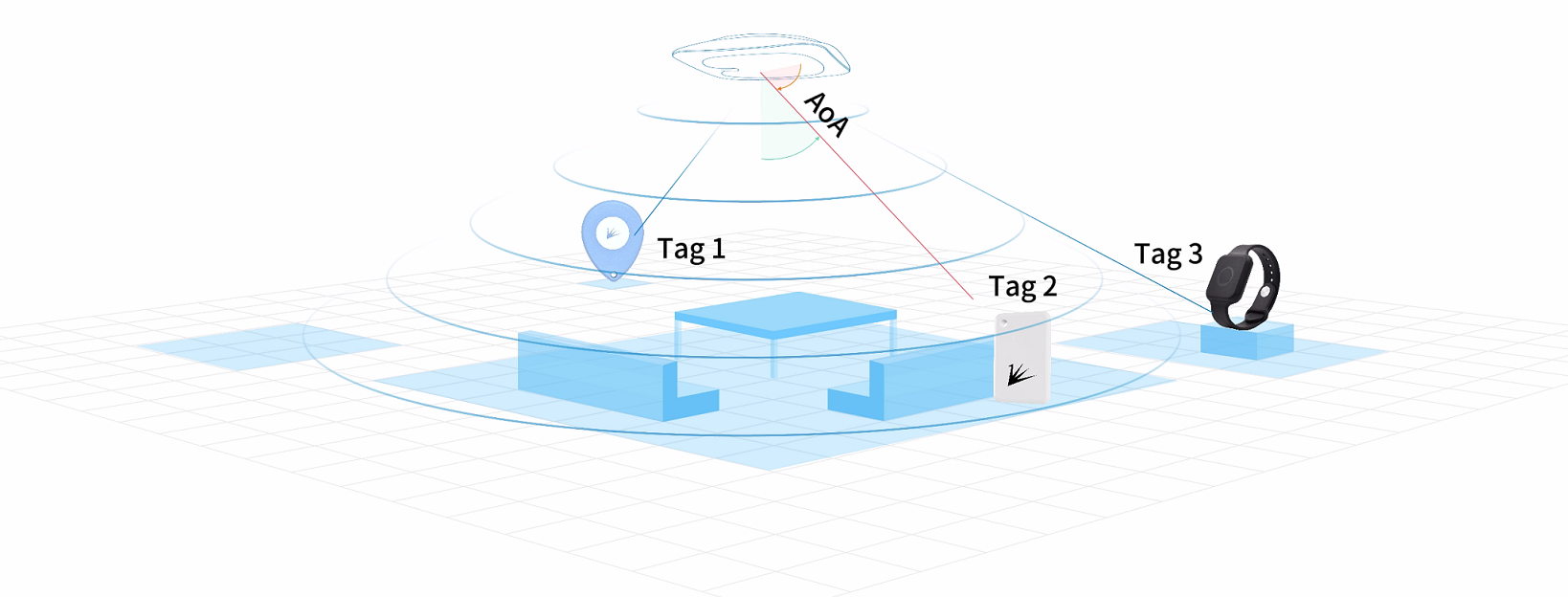
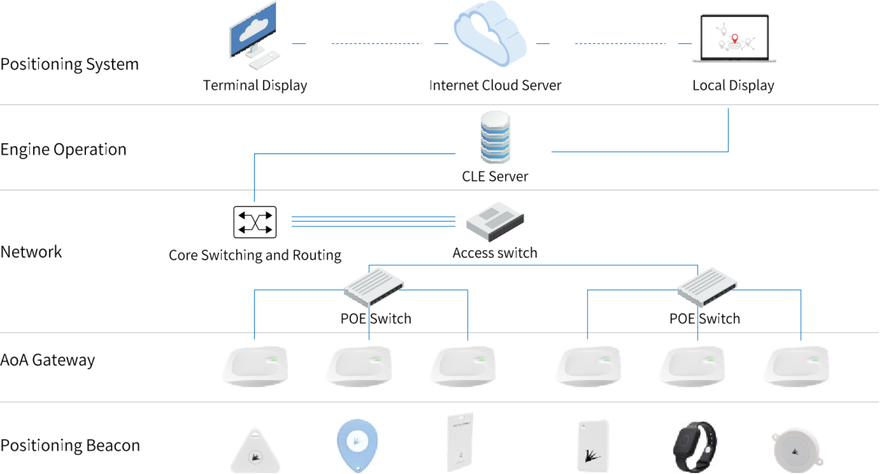
How it works
Positioning beacons broadcast AoA signals.
After receiving the AoA signal, the positioning AoA gateway reports the position information to the positioning engine through the network cable.
The positioning engine reports the positioning result to the positioning service platform.
The positioning service platform can be displayed to the end users according to the positioning results.
RTLS equipment installation and deployment guidance
Preparation before Installation
Before installing the RTLS system, please make sure the following preparations have been completed :
Site Measurement: Measure the dimensions of the installation site to ensure that the site plan is accurate.
Network environment: Verify that there is an available LAN in the venue and that the network connection is stable.
Sample kit: Prepare a RTLS sample kit, including equipment such as positioning beacons and base stations.
Sample Kit Installation Method
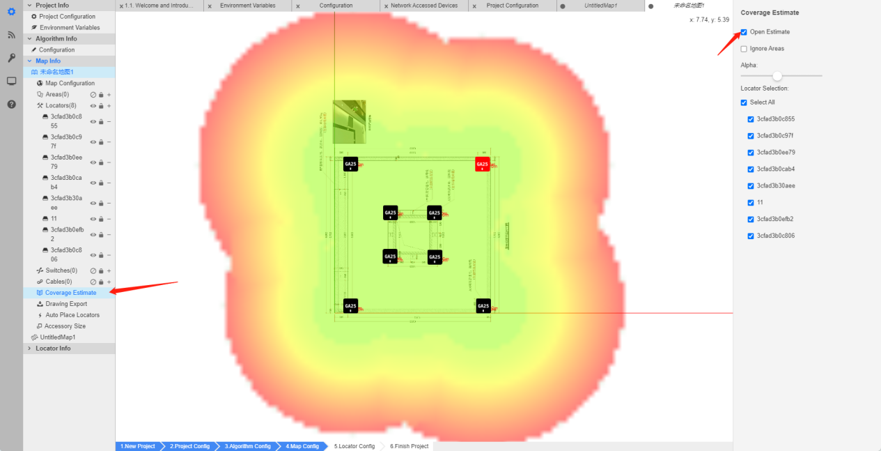
After completing the CCS software configuration (for details, please refer to the AOA Software Operation and Use Instructions), when installation is required, it’s important to pay attention to the installation location and software configuration as far as possible away from obstructions, and the CCS software includes a coverage effect simulation to view the base station coverage area.
Green : Excellent accuracy (0.1-0.2m)
Yellow : Medium accuracy (0.3-0.5m)
Red : Poor accuracy
a) Gateway Introduction
The gateway is divided to two parts, one is the main body part and the other is base part. When installing the gateway, user needs to install the base first, place it horizontally on the ceiling with screws.

main body part
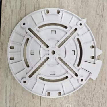
base part
b) Gateway Connection and Power Supply
The gateway has four ports, which supports 12v wired power supply and POE power supply (requires POE-powered switch), the network cable needs to be connected to the POE IN port, as shown below:

If the gateway cannot be searched, please perform RESET operation:
c) Gateway Placement Instructions
Please keep the base station horizontally placed, the CCS software configuration diagram indicates the location of the display lamps. When installing, please install it according to the configuration file. The reference is as follows:
Note
The arrow points to the lights of the base station, both CCS software configuration and filed installation maintain the same direction.

Server Construction
According to the software system requirements, please prepare server computers and client computers that meet the requirements.
1 |
Server operating system and version requirements : |
Win10/Windows Server 2016/Ubuntu 16.04/Centos 7 or above |
2 |
CPU Configuration : |
This can be calculated in CCS with the help of the Server Performance Calculator.
Enter the number of base stations, beacons, and the beacon frequency as shown below to calculate the corresponding server CPU configuration requirements.
Eg, 12-core 3.8GHz or 16-core 2.8GHz.
|
3 |
Network Card : |
Gigabit network card needs to be configured. |
Memory : |
Configure accordingly according to CPU configuration. |
|
5 |
Hard Disk : |
Configured according to the data storage capacity of the business platform. |
6 |
Network equipment installation requirements: |
If the server’s network port requirements have been configured to the Gigabit level,
then the corresponding POE switches, routers and network cables should also be configured to the Gigabit level.
|
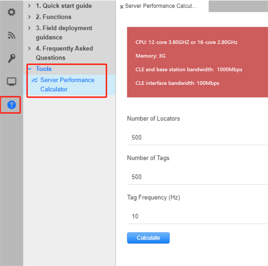
CSS - Server Performance Calculator
Gateway Status Confirmation
Check the status of the base station indicator to ensure that the base station is working properly:
If the indicator does not light up: Check whether the network cable is connected and the power supply is plugged in properly.
If red flashes: Check whether the network cable is normal and whether the IP address is occupied.
If the green flashes slowly: It means the base station already has an IP address. If CCS has not yet scanned it, please check the network connectivity and packet loss issues.
Gateway Installation and Configuration Confirmation
According to the actual situation, field engineers need to confirm the installation height, x, y, z coordinates of each base station one by one (x, y coordinates can be confirmed by referring to the labeling diagram). If you find that there is a difference between the BTS position and the actual installation position, please measure the actual labeling of the BTS and then modify it to the actual position in CCS.
At the same time, confirm whether the direction of the base station is consistent with the project configuration. If any inconsistency is found, please modify it in CCS according to the actual direction. When confirming the base station, user also needs to pay attention to whether the installation requirements of the base station meet the expected standards.
Base station installation precautions
Installation height: The base station should be installed at a height of more than 3 meters to less than 10 meters as far as possible. Avoid obstructions below the installation location, such as chandeliers, metal objects, etc.
Installation direction: All base stations should be installed in accordance with horizontal ceiling mounting with the front facing the floor. The horizontal angle deviation should not exceed 3 degrees. Meanwhile, the installation direction of all BTS should be consistent as far as possible, with the BTS network port as the reference direction to facilitate commissioning and calibration.
Avoid obstacles: The installation location of the base station should avoid obstacles to block interference, such as corners, walls, metal beams and other obstacles that have a greater impact on the base station antenna. There should be no obstacles within 1 meter in front, back, left, right and below the BTS to avoid affecting the positioning effect.
Channel selection: The base station uses 2481 private channel by default, while the sample tag currently uses 2402 Bluetooth channel. The channels of both BTS and tags can be modified within the software. However, it is recommended to use the 2481 private channel to avoid interference by the Bluetooth channel.
AOA Software Operating and Instructions - CCS
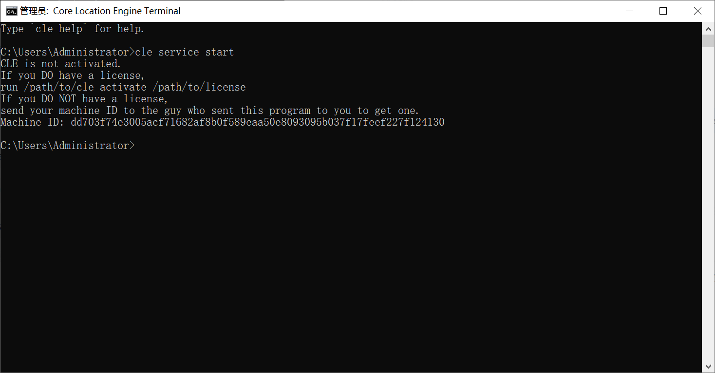
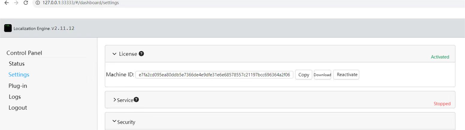
Obtain and Activate License
CCS (Core Config Station) software requires Feasycom to activate the license before using;
Project Information Configuration
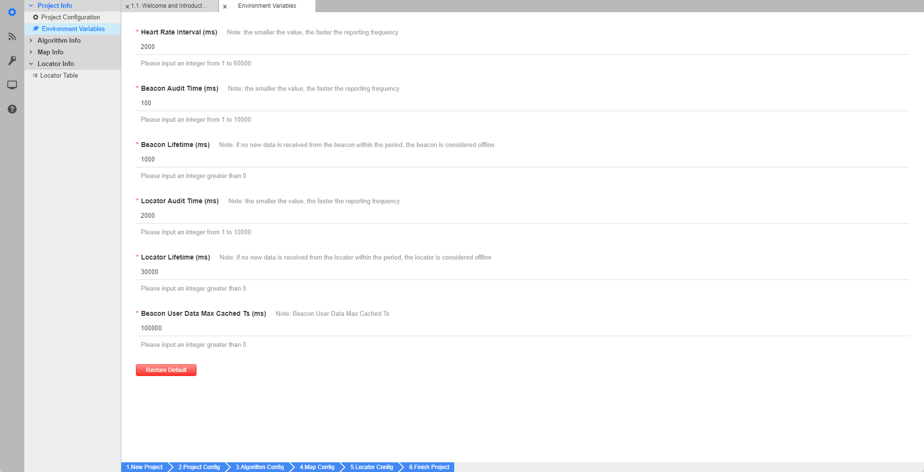
a) Environment Variable Configuration
Open CSS (Core Config Station), after creating a new project, go to Project Info - Environment Variables: The default parameters of the project are large. The following figure shows the configuration parameters that have been verified many times. They can be used directly or adjusted by the users.

CSS(Core Config Station)
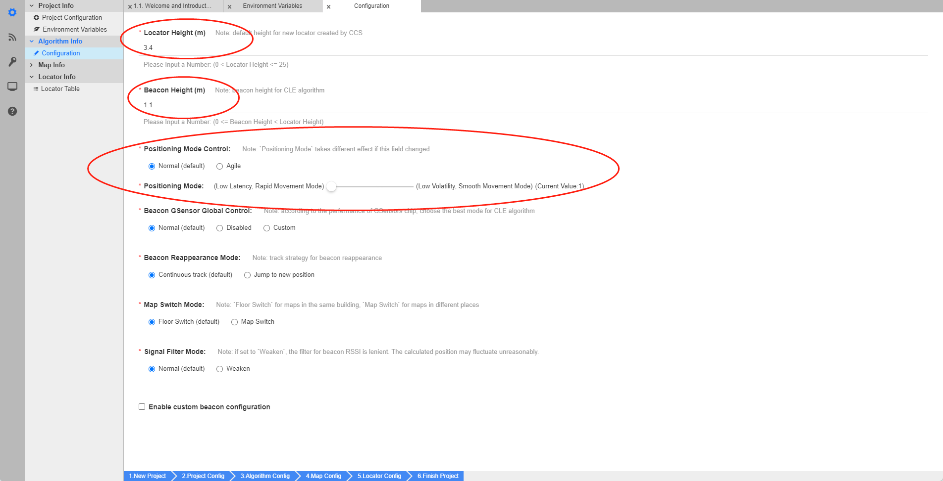
b) Algorithm Information Configuration
In the Project Info - Algorithm Info - Configuration, as shown in the figure below, the parameters in the ellipse area, please adjust them according to the actual situation, users can modify them directly;
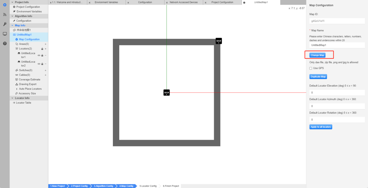
c) Map Configuration- Load Map
In the Project Info - Map Info - Map Configuration, click Change Map to add the required map, the scale must be consistent.
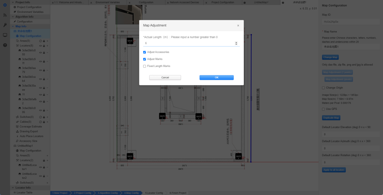
d) Map Configuration- Map Calibration
After changing the map, user needs to perform Map calibration:
Click Map Adjustment (2 Points) , select the 2 Points, and mark the two selected points in the figure below, then the Map Adjustment window pops up– Actual Length, Enter the actual distance, and check lock the marking length.
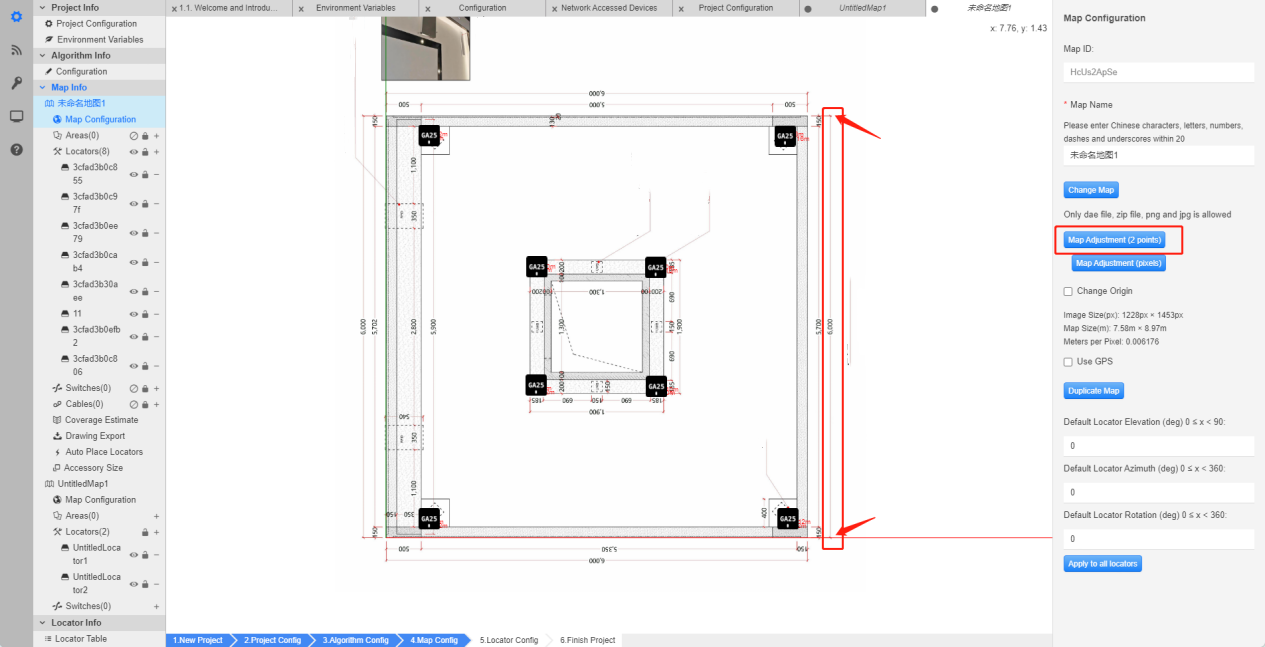
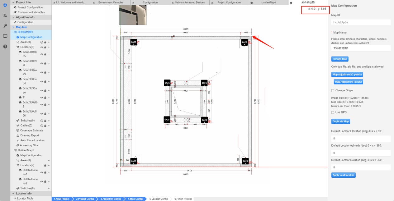
As shown in the picture below, move the mouse to the arrow to view the coordinates.
At this time, user can confirm that the map data is correct. The eg.map size is 6m x 6m.
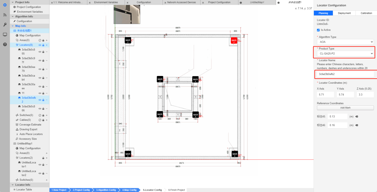
e) Base Station Configuration
In the Base Station Configuration - Planning, choose Product Type & Base station Name. For naming the base station, it’s better to use MAC address of the base station. Fill in the coordinates of the base station (in meters) as appropriate.
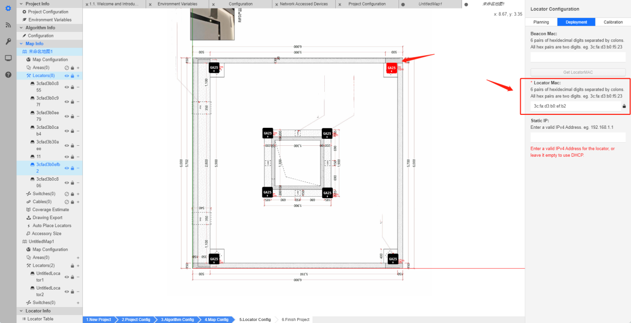
In the Base Station Configuration - Deployment - Locator MAC. Please write the mac address of the base station. It must be consistent with the actual placement. Otherwise, the beacon position will be inaccurate after operation.
f) Simulation Test
After all settings are completed, in the Project Info - Map Info - Coverage Estimate, select Open Estimate to view the coverage after placement.
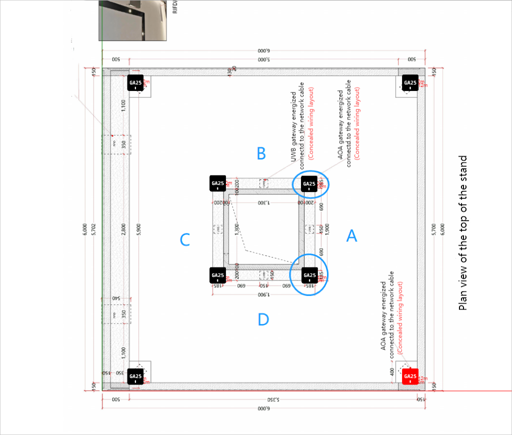
Equipment placement
On the map, each base station will have a point, which is the light on the base station, so the actual placement needs to be based on the actual direction of the map.
Avoid installing in a blocked location.
As shown in the diagram provided, the points on the base station are all facing door D. Therefore, when we stand facing door A, all the lights on the base station are all placed towards left.
Equipement List
a) Network Accessed Devices View
In the Device Management - Network Accessed Devices , the base stations and beacons recognized in the LAN could be viewed.
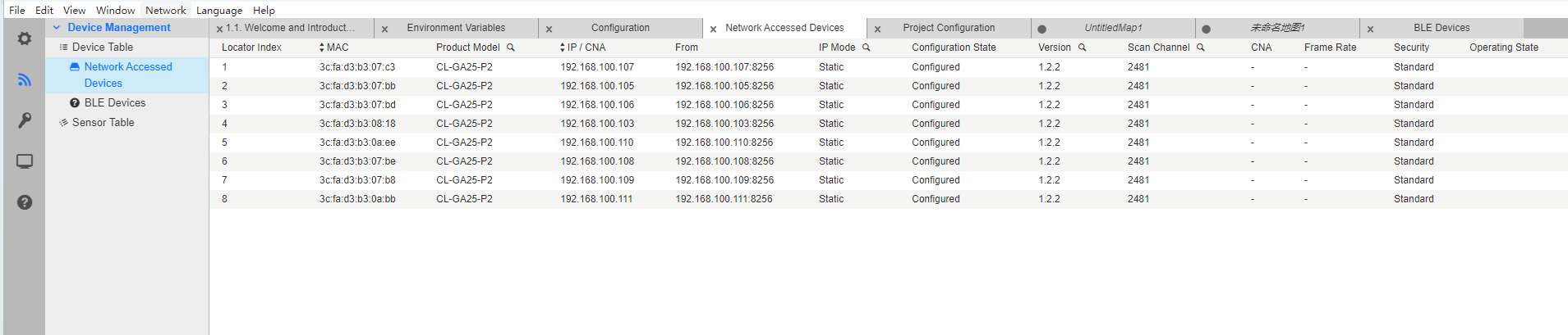
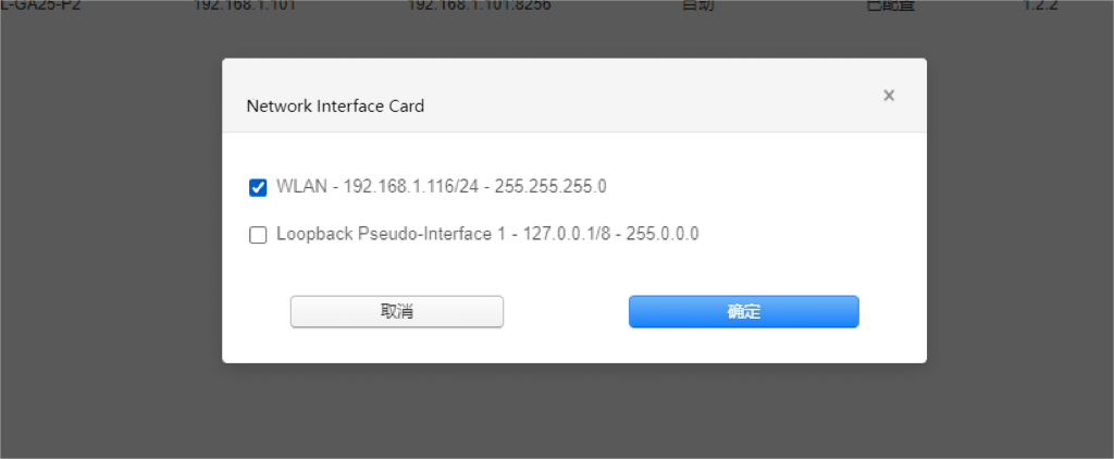
If there is no data, please select Network--NIC--WLAN, and then right-click to refresh.
b) Device Scanning Channel Configuration
The default channel is 2481. User can right-click the base station and beacon to change the channel used, and configure it to Bluetooth channel 2402.
Operate AOA
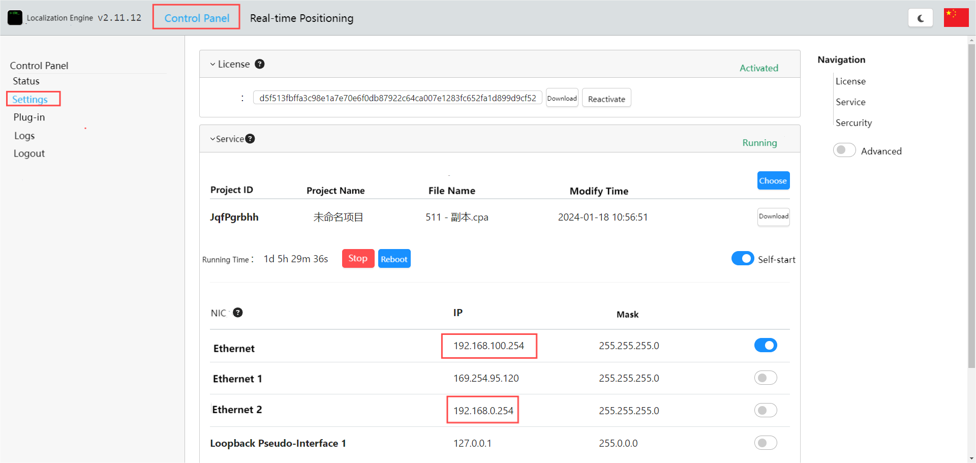
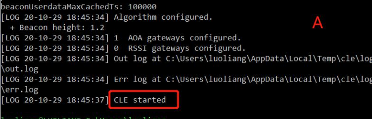
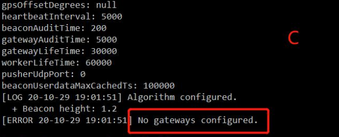
a) Start the project
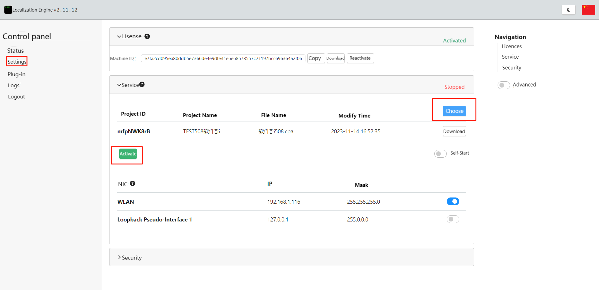
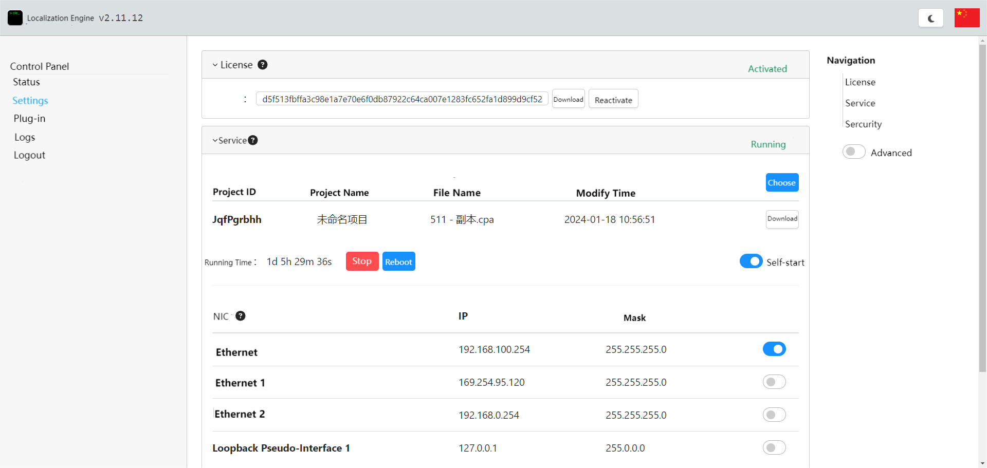
Enter 127.0.0.1:33333 in the browser, go to Positioning Engine - Settings - Services pages, Select the saved .cpa file, then click Start.
b) Real-time track view
After startup, click on real-time positioning to view the trajectory. Click on the beacon or base station to view the data of the beacon or base station.

RTLS Upper Computer Software Pre-Use Instructions - Feasycom RTLS
Pre-use Instructions of The Upper Computer
Before using the RTLS upper computer, please complete the above-mentioned AOA environment setup. After that, user can use the AOA RTLS upper computer.
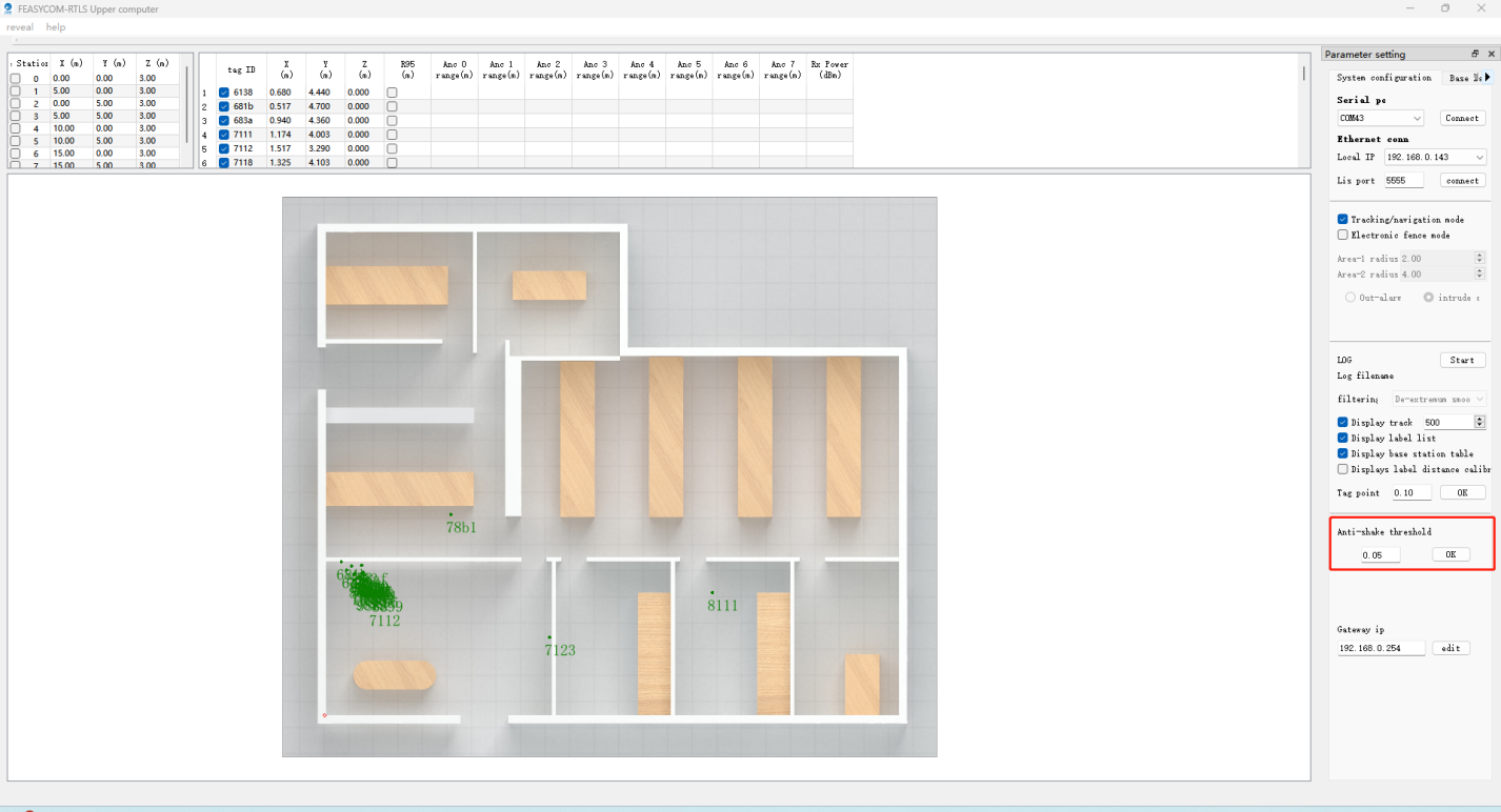
The host computer interface displays
The default display in the RTLS Upper Computer software interface is: Base Station List & Label List . The right sidebar is Parameter Setting toolbar, including system configuration, base map layout, and grid settings. The center of the interface is the actual site map and positioning point display.

Function Introduction
a) Basemap Settings
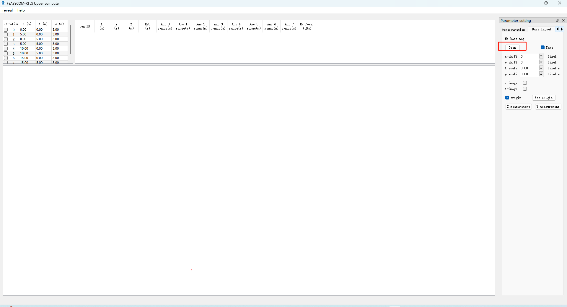
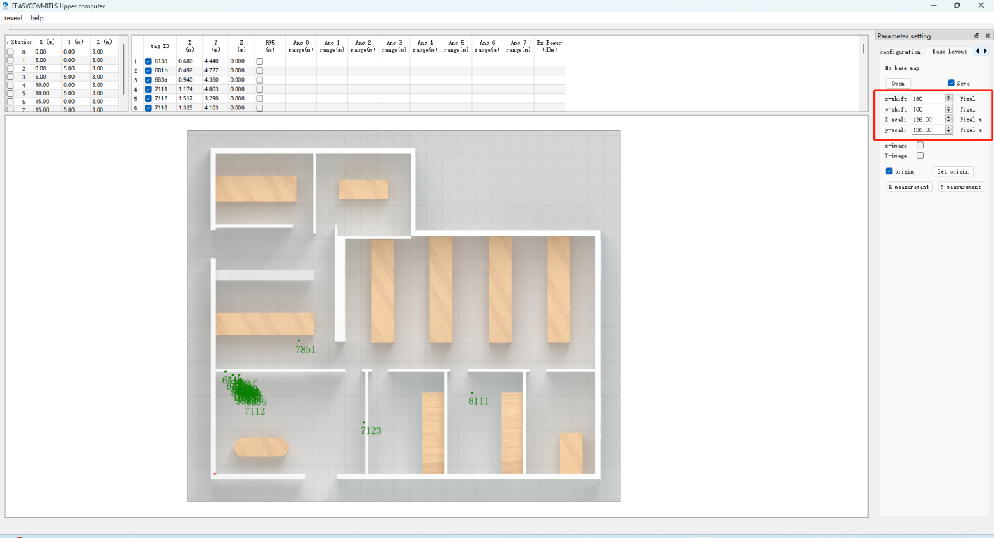
In the Parameter Settings - Base Layout, click Open to open the site layout image. Adjust the image zoom and offset according to the image pixels, so that the positioning points are accurately displayed on the map. If there is no basemap, user can turn on the fence mode.
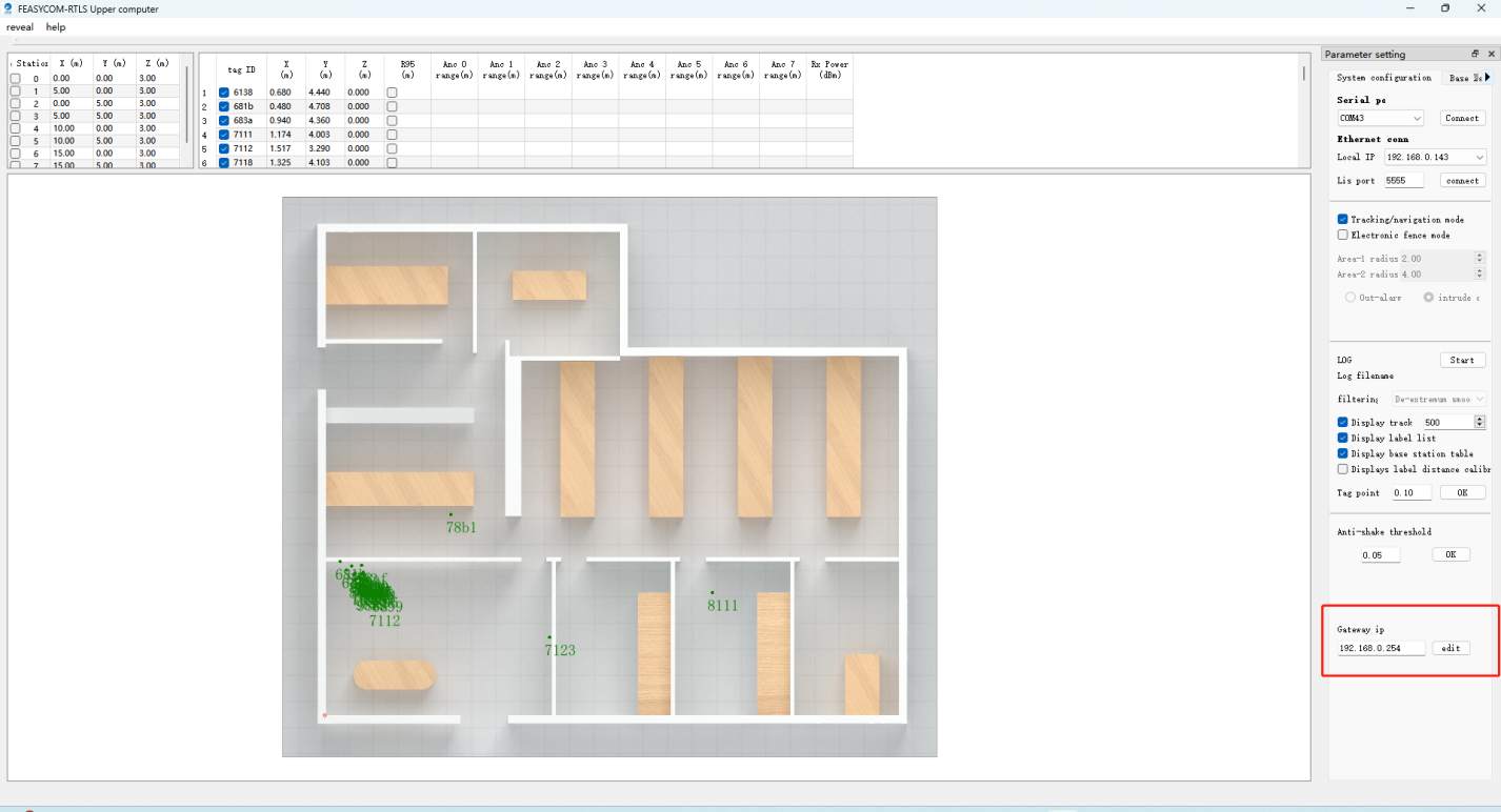
b) Positioning
In the Parameter Settings - System Configuration function column, fill in the IPv4 address of the computer with the AoA software (CSS) installed in the Gateway–IP section, and then click Modify.
Depending on the ip address segment 0 or 100 of the computer used, select the URL to fill in the gateway IP of RTLS. As shown in the image:
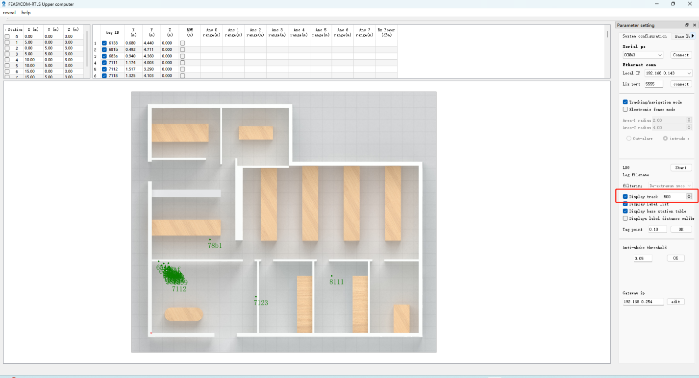
c) Trajectory
The RTLS upper computer can open the trajectory and modify the trajectory length;
In the Parameter Settings - System Configuration function column, check Display Track and fill in the numbers to set the trajectory length, upper limit is 500. As shown in the figure:
d) Anti-shack
RTLS upper computer supports anti-shake adjustment parameters (default 0.05m),
In Parameter Setting - System Configuration - Anti-Shake Threshold item, user can adjust the flutter of the positioning point. The larger the value, the smaller the fluctuation.
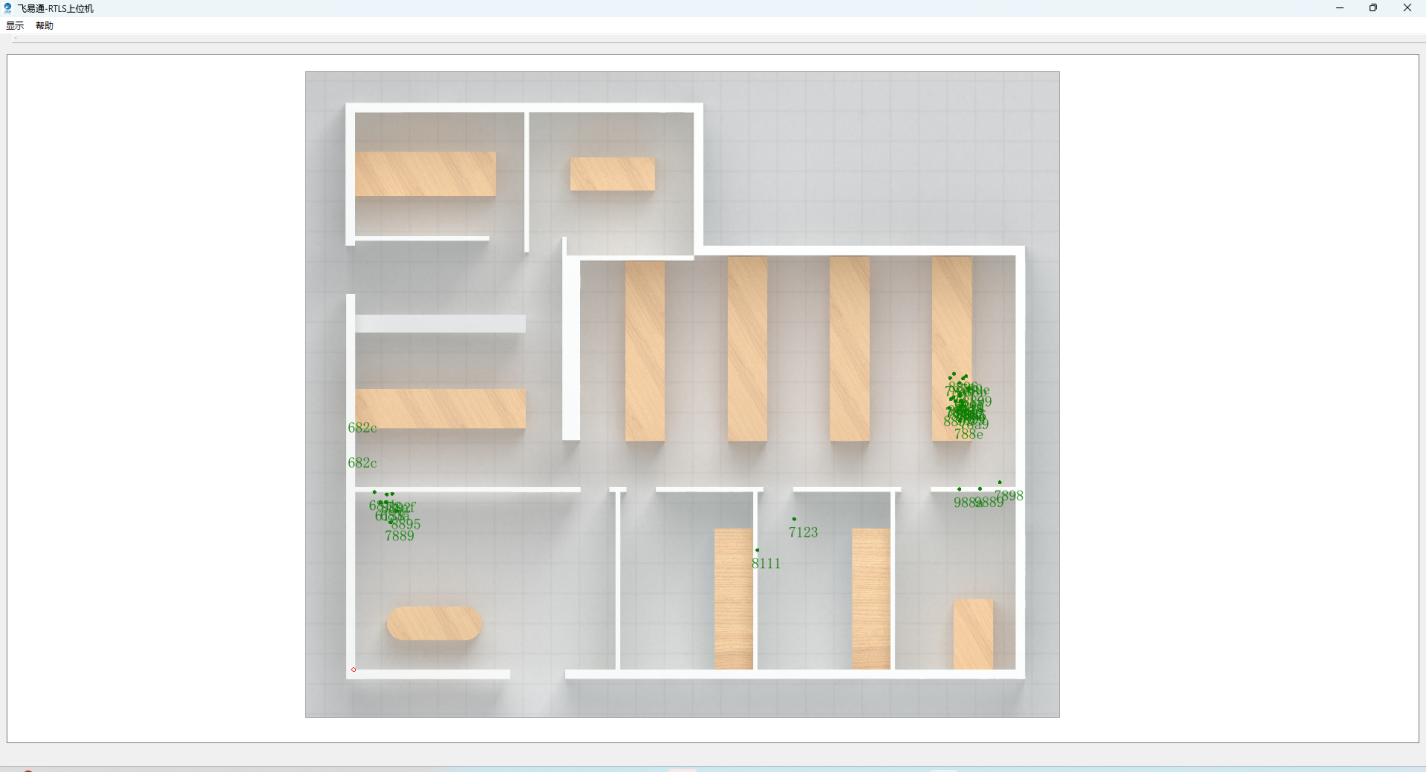
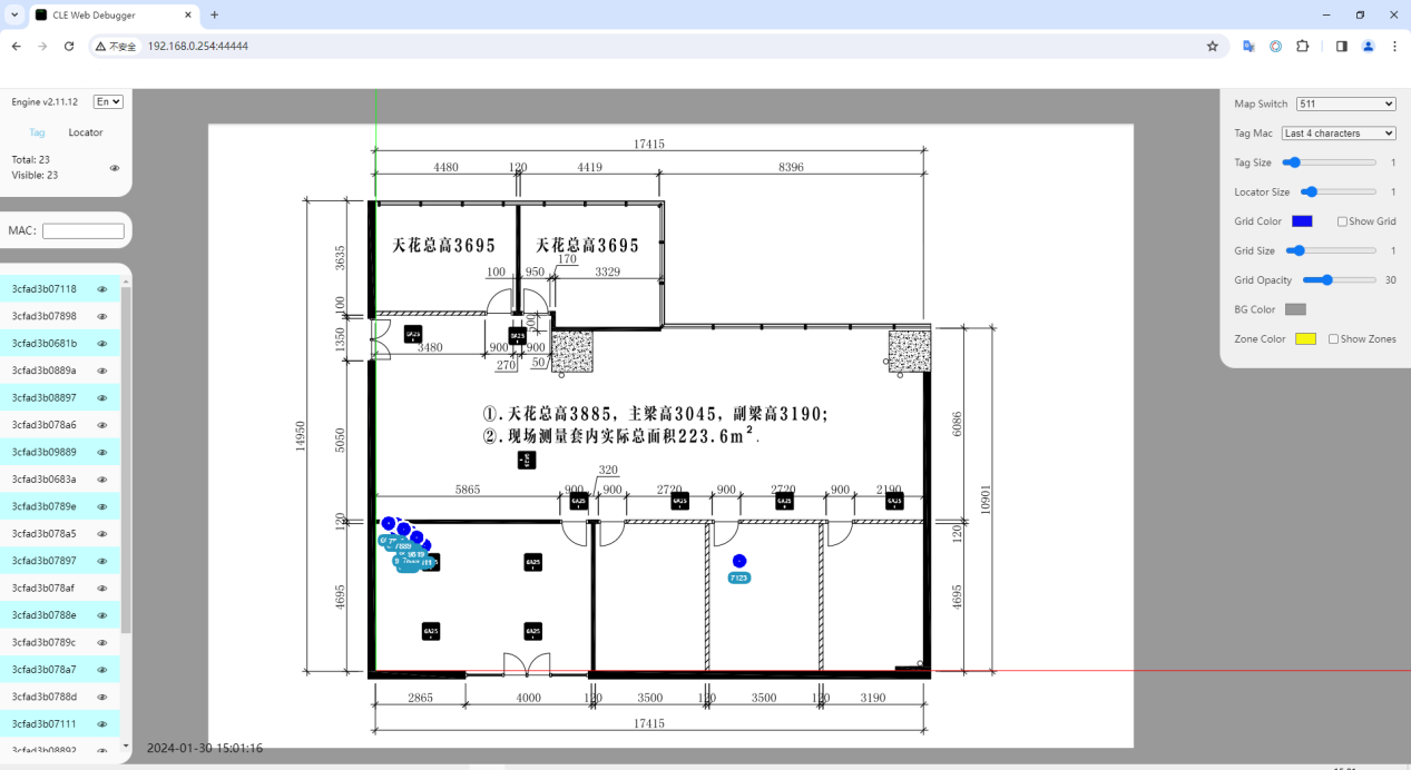
CLE DashBoard Operating Instructions
CLE DashBoard Access
For example, if the IP address of the server/PC that starts the CLE Engine is 192.168.0.254, user can use Chrome to open http://192.168.0.254:44444 on other PCs in the LAN. In this way, it’s easy to access the CLE Dashboard in the LAN.
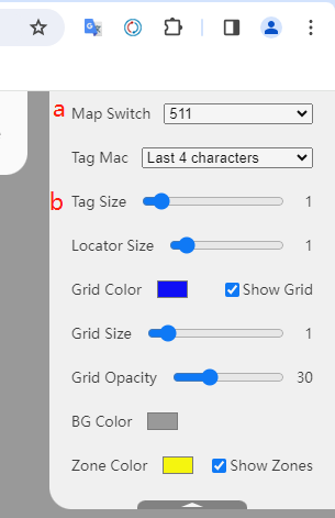
Adjuste Tag Display Size
After entering the CLE Dashboard interface, in the upper right corner of the page:
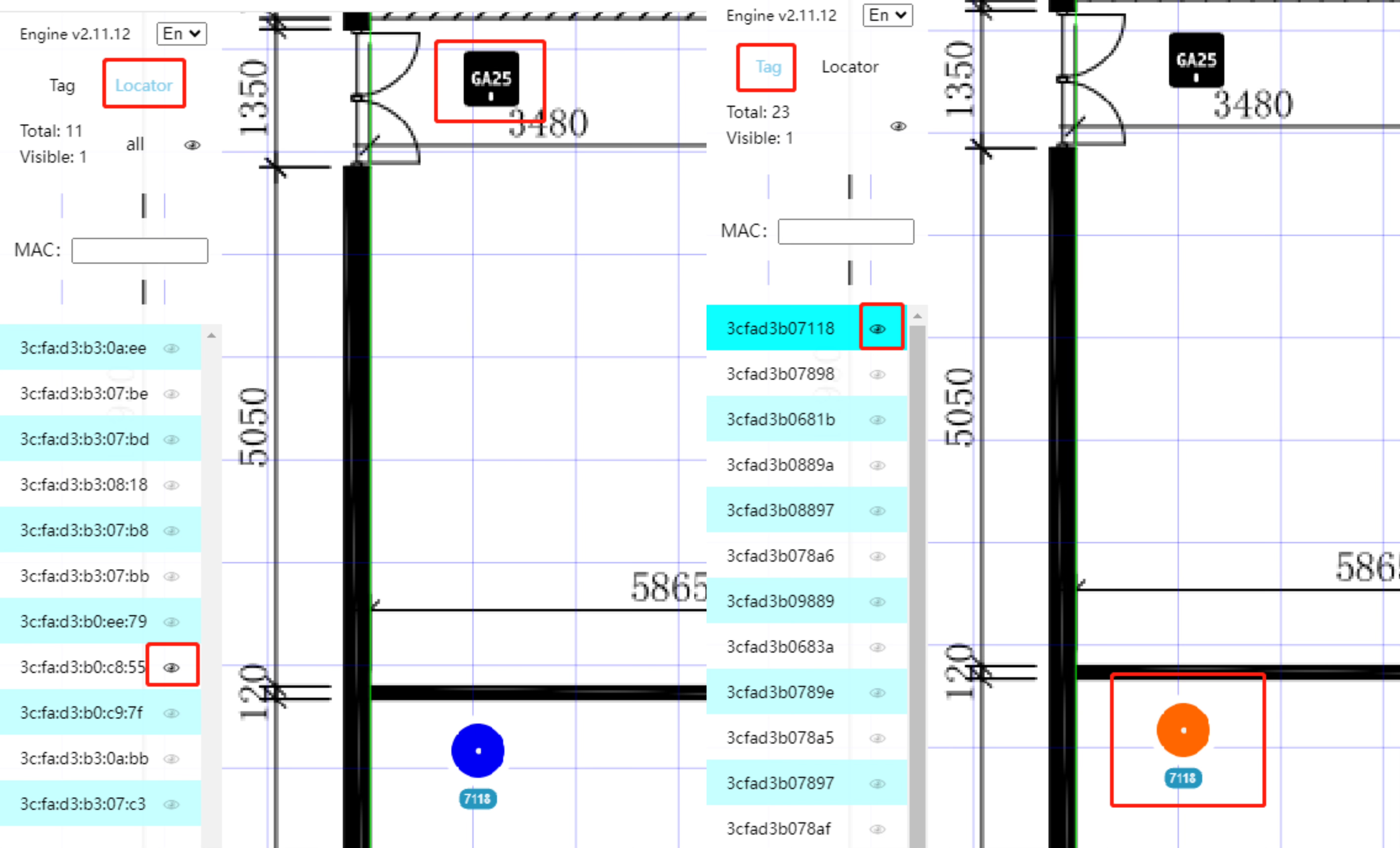
Tag/gateway display
After entering the CLE Dashboard interface, on the left side of the page: click the small eye icon to switch the corresponding tag/gateway display status.
FAQs
Q: Enter http://localhost:44444/ and the browser shows that this site cannot be accessed
Q: CLE Dashboard page Map cannot be displayed
Please use the Chrome browser, if user uses other browsers, it will cause exceptions.
Please check the Chrome version. If the version is too low, the display may be abnormal. Please check for updates. If cannot update, please download and install the new version again: https://www.google.cn/chrome/
Q: CLE Dashboard page–No beacon/The beacon has not been founded
If the map imported in CCS is a 3D map in dae/zip format, please check whether the 3D map contains height information during modeling. If it does, please flatten the z-axis or delete the height.
Please check whether the beacon is turned on. Press it once to see if the indicator light is on. If the light is on, it means it is turned on. If it is not turned on, please press and hold to turn it on.
Please stop the cle engine service: cle service stop, use CCS to open and scan the beacon, then check whether the tag is online and whether the channel is the same as the gateway. If the channel is different, please change the tag to the same channel as the gateway.