FSC-BW236 programming user guide
Introduction
Description
This design guide is suitable for engineers to develop FSC-BW236 Wi-Fi SoC module
Module Default Settings
Bluetooth Mode |
LE-Peripheral |
Bluetooth Name |
FSC-BW236-LE |
Wi-Fi Mode |
STA Mode |
Local AP SSID |
FSC-BW236-AP |
Local AP Password |
12345678 |
Local AP IP Address |
192.168.1.1 |
UART Baudrate |
115200/8/N/1 |
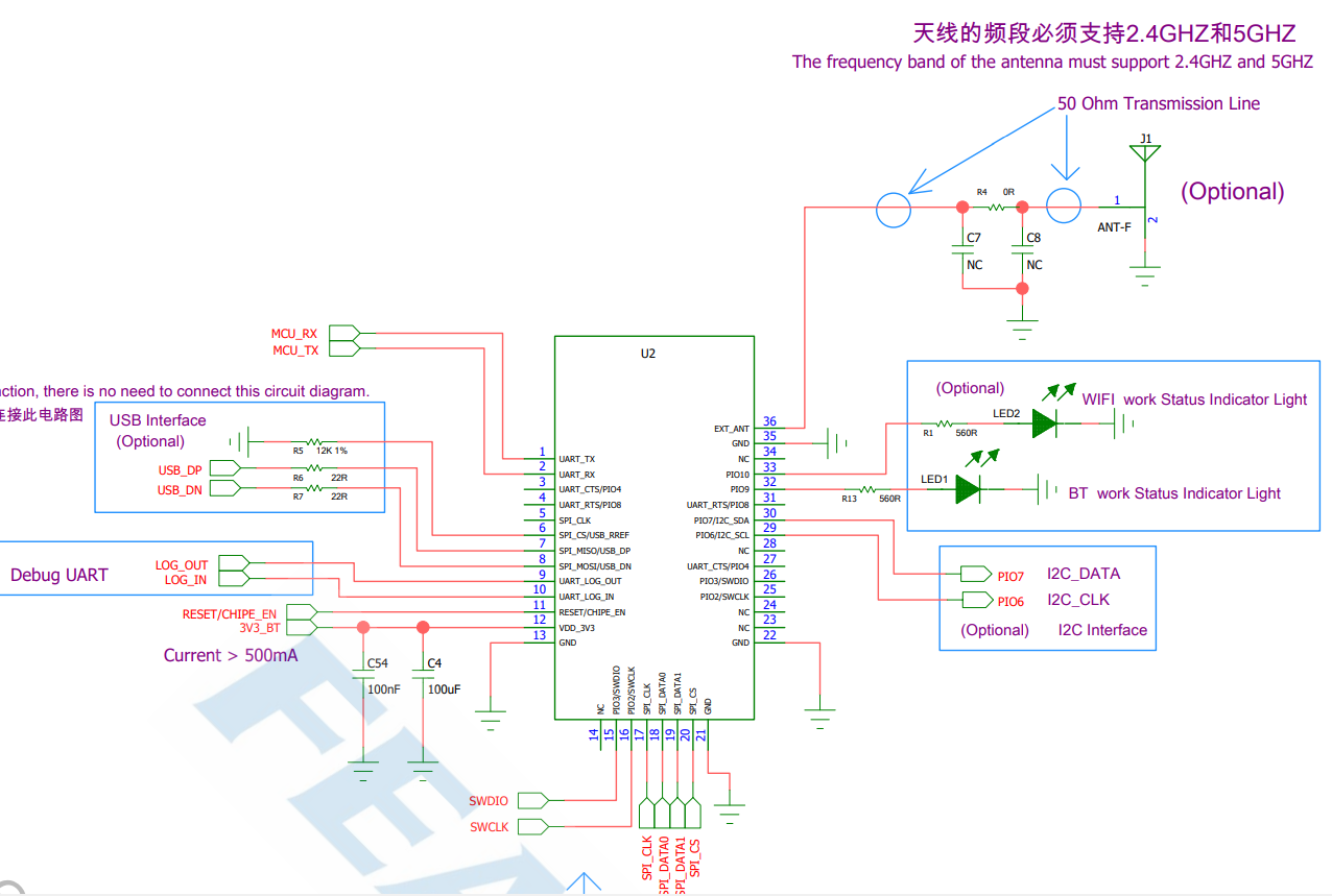
Hardware Description
Pin Figure
Pin Description
Pin |
Pin Name |
Type |
Pin Descriptions |
|---|---|---|---|
1 |
UART_TX |
O |
UART TX |
2 |
UART_RX |
I |
UART RX |
3 |
UART_CTS |
I |
UART CTS(Active High) |
4 |
UART_RTS |
O |
UART RTS(Active High) |
9 |
UARG_LOG_OUT |
O |
DEBUG UART TX |
10 |
UARG_LOG_IN |
I |
DEBUG UART RX |
11 |
RESET/CHIP_EN |
I/O |
RESET, Active Low |
12 |
VDD_3V3 |
VDD |
3.3V Power Supply |
13 |
GND |
VSS |
GND |
21 |
GND |
VSS |
GND |
22 |
GND |
VSS |
GND |
32 |
LED0 |
I/O |
Output High Level When Bluetooth Connected |
33 |
LED1 |
I/O |
Output High Level When Wi-Fi Connected |
35 |
GND |
VSS |
GND |
36 |
EXT_ANT |
ANT |
Antenna Option |
Hardware Design Notes
Module only needs to connect VDD/GND/UART_RX/UART_TX for a simple test
Programming manual only provides a simple description of the IO port. For more detailed description, please refer to the hardware design document
Feasycom is glad to review your schematic diagram for a best result of Bluetooth/Wi-Fi distance
Function Description
Hardware Interface
GPIO
PWM
UART
SPI SLAVE
I2S Master/Slave
Analog Input/Output
Profiles & Features
Bluetooth
GATTS (Generic Attribute Profile LE-Peripheral role)
GATTC (Generic Attribute Profile LE-Central role)
Wi-Fi
TCP (Transmission Control Protocol)
UDP (USER Datagram Protocol)
HTTP (Hypertext Transfer Protocol)
MQTT (Message Queuing Telemetry Transport)
WEB SOCKET
Command Description
Specification
{} : Content between {} is optional
<< : Content behind << represents a COMMAND from Host
>> : Content behind >> represents a RESPONSE/EVENT to Host
Command Format
All commands start with “AT”, end with <CR><LF>
<CR> means “carriage return”, corresponds to hex value 0x0D
<LF> means “line feed”, corresponds to hex value 0x0A
If Command has Parameter, Parameter follows behind ‘=’
If Command has multiple Parameters, Parameter must be separated by ‘,’
If Command has Response, Response starts with <CR><LF>, ends with <CR><LF>
Module will always report command’s execution result by using OK for success or ERR<code> for failure
Error Code |
Meaning |
|---|---|
001 |
Failed |
002 |
Invalid parameter |
003 |
Invalid state |
004 |
Command mismatch |
005 |
Busy |
006 |
Command not supported |
007 |
Profile not turned on |
008 |
No memory |
Others |
Reserved for future use |
Event Format
All Events start with <CR><LF>, end with <CR><LF>
If Event has Parameter, Parameter follow behind ‘=’
If Event has multiple Parameters, Parameter must be separated by ‘ , ’
Commands Table
General Commands
AT - UART Test Command
Command |
AT |
Response |
OK |
Description |
Test whether the UART is working |
AT+VER - Read Firmware Version
Command |
AT+VER |
Response |
+VER=Param1,Param2 |
|
Module Type |
|
Firmware Version |
AT+BAUD - Read/Write UART Baudrate
Command |
AT+BAUD{=Param} |
|
2400/4800/9600/19200/38400/57600/115200(default)/128000/
230400/256000/460800/512000/921600/1000000/1382400
2000000/3000000/4000000/5000000/6000000
|
Response |
+BAUD=Param |
|
All baudrates supported by current module |
Description |
Baudrate will be changed after module reboot |
AT+TPMODE - Read/Write Throughput Mode
Command |
AT+TPMODE{=Param} |
|
1:Enable
0:Disable
|
Response |
+TPMODE=Param |
|
Module’s current throughput mode |
Description |
When TCP/GATT profile connected and throughput mode is on,
the AT command will be de-active,
every byte received via physical UART will be sent to air, vice versa
|
AT+LPM - Enter Low Power Mode
Command |
AT+LPM{=Param} |
|
1:Enter Light Sleep
2:Enter Deep Sleep
|
Response |
OK |
Description |
After module enters lignth sleep, it maintains connection with the hotspot and TCP,
and can be waked up through WLAN RX data. The power consumption is about 30mA.
After module enters deep sleep, all functions will be stopped and the power consumption is about 10uA.
Pull up the 7th pin of the module to wake up.
|
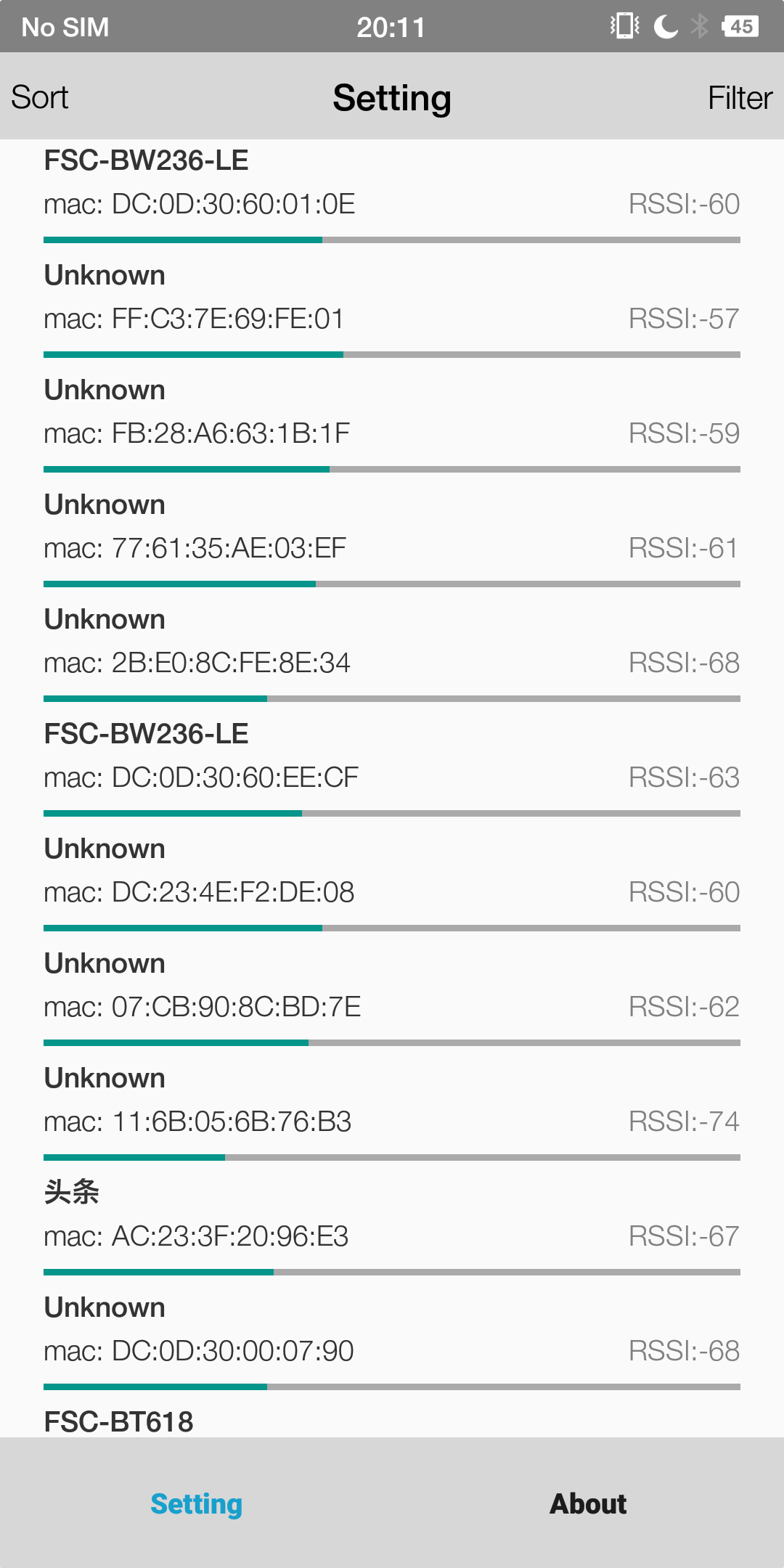
AT+SCAN - Scan Devices
Command |
AT+SCAN=Param1{,Param2}{,Param3} |
|
5:Scan AP around
1:Scan BLE devices
0:Stop Scanning
|
|
Only take effect when scanning BLE devices
scan duration (unit: second) is specified
After a timeout, module stops scaning
|
|
Only take effect when scanning BLE devices
BLE device’s name is specified
After a timeout, module stops scanning
|
Response |
+SCAN=param1,param2,param3,param4,param5,param6 |
|
Scan AP: Sequence Numbers
Scan BlE device: Sequence Numbers
|
|
Scan AP: 5(changeless)
Scan BLE device:BLE device address type
|
|
Scan AP: AP’s MAC address
Scan BLE device: BLE device’s MAC address
|
|
Scan AP: RSSI for module and AP
Scan BLE device: RSSI for module and BLE device
|
|
Scan AP: Length of AP’s SSID
Scan BLE device: Length of BLE device’s name
|
|
Scan AP: AP’s SSID
Scan BLE device:BLE device’s name
|
Description |
Scan AP: in STA Mode
Scan BLE device:in Central Mode
|
AT+REBOOT - Software Reset
Command |
AT+REBOOT |
Response |
OK |
Description |
Module Reboot |
AT+RESTORE - Restore Factory Setting
Command |
AT+RESTORE |
Response |
OK |
Description |
Module restore all factory settings then reboot |
AT+BTEN - Enable/Disable Bluetooth
Command |
AT+BTEN{=Param} |
|
1: Enable
0: Disable
|
Description |
Only take effect immediately |
AT+STAT - Read Connection Status
Command |
AT+STAT |
Response |
+STAT=Param1, Param2, Param3, Param4, Param5, Param6, Param7 |
|
Connection Status in BLE Peripheral Mode |
|
Connection Status in BLE Central Mode |
|
Connection Status to Access Point |
|
Connection Status as Tcp Server |
|
Connection Status as Tcp Client |
|
Connection Status as SSL client |
|
Connection Status as MQTT client |
Description |
0: uninitialized
1: ready
2: connecting
3: connected
|
AT+DSCA - Disconnect From AP or BLE Device
Command |
AT+DSCA=Param |
|
1:Disconnect the module from the AP
2:Disconnect the module from the BLE device
|
Response |
OK |
Description |
Command can be used only in STA mode or Peripheral mode. |
Bluetooth Command
AT+ADDR/LEADDR - Read Bluetooth MAC
Command |
AT+ADDR/LEADDR |
Response |
+ADDR/LEADDR=Param |
|
Module’s LE MAC address (12 Bytes ASCII) |
Description |
Only Read Supported |
AT+NAME/LENAME - Read/Write Bluetooth BLE Name
Command |
AT+NAME/LENAME{=Param1{,Param2}} |
|
BLE local name(1~25 Bytes ASCII) |
|
MAC address suffix(0/1,default:1)
0-Disable suffix
1-Enable suffix “-XXXX” (lower 4 bytes of MAC address) after local name
|
Response |
+NAME/LENAME=Param |
Description |
AT+GATTSEND - Send BLE Data in Peripheral Mode
Command |
AT+GATTSEND=Param1,Param2 |
|
Payload length (1~999) |
|
Payload (1~999 Bytes UTF8) |
Response |
OK |
Description |
If throughput mode is enable, this command is de-active |
AT+MODE: Read/Write Bluetooth Mode
Command |
AT+MODE{=Param} |
|
0: BLE Peripheral
1: BLE Central
|
Response |
+MODE=Param |
Description |
Module will reboot after setting |
AT+LECONN - Connect to Remote BLE Device in Central Mode
Command |
AT+LECONN=Param1,Param2 |
|
BLE device’s MAC address type(0:public,1:random) |
|
BLE device’s MAC address |
Response |
OK |
Description |
Only take effect in BLE Central Mode |
AT+GATTAC - Read/Write Auto Connection Setting in BLE Central Mode
Command |
AT+GATTAC{=Param} |
|
0: Disable
1: Enable(default)
|
Response |
+GATTAC=Param |
Description |
Only take effect after reboot |
AT+LESEND - Send Data in BLE Central Mode
Command |
AT+LESEND=Param1,Param2 |
|
Payload length (1~999) |
|
Payload (1~999 Bytes UTF8) |
Response |
OK |
Description |
If throughput mode is enable, this command is de-active |
AT+GATTSTAT - Read Connection Status
Command |
AT+GATTSTAT |
Response |
+GATTSTAT=Param1 |
|
Connection Status in BLE Peripheral/Central Mode |
Description |
0: uninitialized
1: ready
2: connecting
3: connected
|
AT+TYPE - Read/Write BLE Connectition Type
Command |
AT+TYPE{=Param} |
|
0:Unbound
1:Binding without PIN code
2:Bingding with PIN code
|
Response |
+TYPE=Param |
|
Module’s GATT connection type |
AT+PIN - Read/Write Bluetooth BLE PIN Code
Command |
AT+PIN{=Param1} |
|
BLE local PIN Code(32 - bit unsigned integer number) |
Response |
+PIN=Param |
Description |
Wi-Fi Command
AT+ROLE - Read/Write Wi-Fi Mode
Command |
AT+ROLE{=Param} |
|
1:STA Mode
2:AP Mode
3:STA+AP Concurrent Mode
|
Response |
+ROLE=Param |
Description |
Module will reboot after setting |
AT+RAP - Read Connected AP’s information/Connect to Remote AP
Command |
AT+RAP{=Param1}{,Param2} |
|
AP’s SSID |
|
AP’s password,if way of encryption is OPEN, no need to set this parameter |
Response |
+RAP=Param1,Param2 |
Description |
This command can be used in STA mode or STA+AP concurrent mode
Module adapts different encryption ways automatically
|
AT+BRAP - Connect to AP by BSSID
Command |
AT+BRAP{=Param1}{,Param2} |
|
AP’s BSSID(MAC address) |
|
AP’s password,if way of encryption is OPEN, no need to set this parameter |
Response |
+BRAP=Param1,Param2 |
Description |
This command can be used in STA mode or STA+AP concurrent mode
Module adapts different encryption ways automatically
|
AT+CAP - Clear Connected AP’s Information
Command |
AT+CAP |
|
None |
Response |
OK |
Description |
Clear Connected AP’s Information |
AT+BSSID - Read Connected AP’s BSSID
Command |
AT+BSSID |
Response |
+BSSID=Param |
Description |
If “ERR003” is returned, it indicates that the module is not currently connected to the AP |
AT+LIP - Read Current Local IP Address
Command |
AT+LIP |
Response |
+LIP=Param |
Description |
If “0.0.0.0” is returned, it indicates that the module is not currently connected to the AP |
AT+MDNSEN - Enable/Disable MDNS Function
Command |
AT+MDNSEN{=Param} |
|
0: Disable(default)
1: Enable
|
Response |
+MDNSEN=Param |
AT+DHCP - Read/Write IP Distribution Mode
Command |
AT+DHCP{=Param} |
|
0:Use static IP
1:Use dynamic IP(default)
|
Response |
+DHCP=Param |
Description |
If a static IP address is used for connection, ensure that the static IP address, mask, gateway, and DNS Settings are correct.
Otherwise, network communication may be interrupted
|
AT+SIP - Read/Write Static IP
Command |
AT+SIP{=Param} |
|
IPV4 Address |
Response |
+SIP=Param |
Description |
This command can be used when +DHCP=0 |
AT+GW - Read/Write Gateway
Command |
AT+GW{=Param} |
|
IPV4 Address |
Response |
+GW=Param |
Description |
This command can be used when +DHCP=0 |
AT+MASK - Read/Write Subnet Mask
Command |
AT+MASK{=Param} |
|
IPV4 Address |
Response |
+MASK=Param |
Description |
This command can be used when +DHCP=0 |
AT+DNS - Read/Write DNS Address
Command |
AT+DNS{=Param} |
|
IPV4 Address |
Response |
+DNS=Param |
Description |
This command can be used when +DHCP=0 |
AT+APAC - Read/Write Automatically Connect to AP
Command |
AT+APAC{=Param} |
|
0:Disable
1:Enable(default)
|
Response |
+APAC=Param |
Description |
This command can be used when +ROLE=1 or 3 |
AT+RSSI - Read Signal Strength Between Module And AP
Command |
AT+RSSI |
Response |
+RSSI=Param |
|
RSSI value (-99 ~ 0) |
Description |
The result of RSSI is 0 when disconnect from AP. |
AT+STAMP - Read Time Stamp
Command |
AT+STAMP |
Response |
+STAMP=Param |
|
value (unit:second) |
Description |
Module needs to access the Internet,otherwise it will fail. |
AT+MAC - Read Wi-Fi MAC Address
Command |
AT+MAC |
Response |
+MAC=Param |
|
Wi-Fi MAC Address(12 Bytes ASCII) |
Description |
MAC address can only be read , not be written |
AT+SCFG - Simple Config
Command |
AT+SCFG=Param |
|
1:Start Simple Config
2:Start Air-Kiss Config
0:Stop Simple Config
|
Response |
OK |
Note |
This command should be used with FeasyWiFi and Airkiss APP |
AT+WEBCFG - WEB Config
Command |
AT+WEBCFG=Param |
|
1:Start WEB Config
0:Stop WEB Config
|
Response |
OK |
Description |
This command can be used when +ROLE=2 |
AT+WPSCFG - WPS Config
Command |
AT+WPSCFG=Param |
|
1:Start WPS Config |
Response |
OK |
AT+LAP - Read/Write AP Mode Configuration
Command |
AT+LAP{=Param1,Param2,Param3} |
|
The SSID of the module as a AP |
|
The password of the module as a AP |
|
The IP address of the module as a AP |
Response |
+LAP=Param1, Param2, Param3 |
Description |
If the module is configured as a AP with OPEN encryption,
no need to set the Param2,
such as AT+LAP=FSC-BW236-AP,192.168.1.1
|
TCP Command
AT+SOCK - Read/Write SOCKET
Command |
AT+SOCK{=Param1,Param2,Param3,
Param4}
|
|
Protocol Type(TCPS,TCPC,UDP,SSL) |
|
Port of Module |
|
Remote Address |
|
Remote Port |
Response |
+SOCK=Param1, Param2, Param3, Param4 |
Description |
The TCP SERVER is enabled after power on, default port is 9100
Param3 and Param4 can be omitted if module works as a TCP Server or a UDP
|
AT+WLANC - Start SOCKET/MQTT
Command |
AT+WLANC=Param |
|
3:Connection with TCP/UDP/SSL
4:Connection with MQTT or cloud platform
5:Connection with WEB Socket
|
Response |
OK |
Description |
This command can only be used after the SOCKET or MQTT configuration is completed |
AT+MAXCON - Read/Write Max Connections As TCP Server
Command |
AT+MAXCON=Param |
|
Max Connections |
Response |
+MAXCON=Param |
Description |
Default Max Connections is 3 |
AT+WFSEND - Send SOCKET Data to Remote Device
Command |
AT+WFSEND=Param1,Param2,Param3 |
|
TCP/UDP Connection ID |
|
Payload length (1~999) |
|
Payload (1~999 Bytes UTF8) |
Response |
OK |
Description |
When the module is used as TCP server, it can be connected by 3 remote clients and connection ID is 0,1,2;
When the module is used as TCP client, the ID is 3;
When the module is UDP, the ID is 4.
The connection ID will vary with the MAXCON setting,
such as the MAXCON is 6, the ID as TCP Server is 0 ~ 5,
and the ID as the TCP Client is 6, the ID as UDP is 7
|
AT+CLOSE - Close Connection as TCP client
Command |
AT+CLOSE |
Response |
OK |
Description |
This command can be used to disconnect from a remote TCP Server,if module works as a TCP Client |
WEBSOCKET Command
AT+WEBSOCK - Read/Write WEBSOCKET Address
Command |
AT+WEBSOCK=Param1,Param2 |
|
WSC : Module works as Client
WSS : Module works as Server
|
|
Remote Server Address if Module works as Client
Local IP Address if Module works as Server
|
Response |
+WEBSOCK=Param1,Param2 |
Description |
Param2 should start with ws:// or wss://, |
Note
PORT configuration can be omitted.80 is default for ws,433 is default for wss
WEBSOCKET and TCP can’t be used at the same time.
AT+WSSEND - Send Websocket Data
Command |
AT+WSSEND=Param1{,Param2},Param3,Param4 |
|
WSC : Module works as Client
WSS : Module works as Server
|
|
Specify the client ID. This parameter is only required if the module works as Server |
|
Payload length |
|
Payload |
Response |
OK |
Description |
Module supports one Client by default if works as Server. Therefore, Param2 is 1 when sending data |
AT+WSCLS - Close Websocket
Command |
AT+WSCLS |
Response |
OK |
Description |
Close Connection With Websocket |
AT+WSSTAT - Read Websocket Status
Command |
AT+WSSTAT |
Response |
+WSSTAT=Param1,Param2 |
Description |
0: uninitialized
1: ready
2: connecting
3: connected
Param1: Module’s websocket status when works as Client
Param2: Module’s websocket status when works as Server
|
HTTP Command
AT+HTTP - Access the HTTP Server
Command |
AT+HTTP=Param1,Param2,Param3{,Param4} |
|
HTTP Request Method, only support GET and POST |
|
HTTP server’s address |
|
HTTP server’s URI |
|
Resume breakpoint to support
This Parameter can be omitted.
Format is “Range:bytes=starting byte-ending byte”
|
Response |
OK |
Description |
AT+HTTP is used to access HTTP server
AT+HTTPS is used to access HTTPS server
The default port of HTTP server is 80, default port of HTTPS server is 443
Param2 can be set like this “x.x.x.x:port” ,if port of server need to be specified
|
Note
“http://httpbin.org” is available for testing HTTP
MQTT Command
AT+BROKER - Read/Write MQTT broker
Command |
AT+BROKER{=Param} |
|
MQTT server address |
Response |
+BROKER=Param |
Description |
“gpssensor.ddns.net” is available for testing MQTT |
AT+CLIENTID - Read/Write MQTT Client ID
Command |
AT+CLIENTID{=Param} |
|
MQTT Client ID |
Response |
+CLIENTID=Param |
AT+USERNAME - Read/Write MQTT USERNAME
Command |
AT+USERNAME{=Param} |
|
MQTT USERNAME |
Response |
+USERNAME=Param |
AT+MQTTPWD - Read/Write MQTT password
Command |
AT+MQTTPWD{=Param} |
|
MQTT MQTTPWD |
Response |
+MQTTPWD=Param |
AT+SUBTPC - Read/Subscribe MQTT Topic
Command |
AT+SUBTPC{=Param1,Param2} |
|
Topic |
|
QOS, only can be 0,1,2 |
Response |
+SUBTPC=Param1,Param2 |
Note
The command will return an error if the same topic is subscribed repeatedly
Maximum of five different subscribed topics is 5
AT+UNSUBTPC - Unsubscribe Specify MQTT Topic
Command |
AT+UNSUBTPC=Param |
|
Specify the topic to be unsubscribed |
Response |
OK |
Description |
There is no need to specify a QoS value when unsubscribes |
AT+UNSUBALL - Unsubscribe All MQTT Topics
Command |
AT+UNSUBALL |
Response |
OK |
AT+MQTTSEND - Send MQTT Data
Command |
AT+MQTTSEND=Param1,Param2,Param3,Param4 |
|
Publish Topic |
|
QOS(0,1,2) |
|
Payload length |
|
Payload |
Response |
OK |
AT+MQTTMODE - Read/Write MQTT Mode
Command |
AT+MQTTMODE{=Param} |
|
0: Connect to general MQTT Server(default)
1: Connect to Ali Cloud Platform
2: Connect to QCloud Platform(Tencent)
|
Response |
OK |
Description |
Module connects to different cloud platforms by switching MQTT modes |
AT+MQTTS - Enable/Disable MQTT with SSL/TLS
Command |
AT+MQTTS{=Param} |
|
0: Disable(default)
1: Enable
|
Response |
+MQTTS=Param |
AT+MQTTPORT - Read/Write MQTT Port
Command |
AT+MQTTPORT{=Param} |
|
MQTT port, default is 1883 |
Response |
+MQTTPORT=Param |
Description |
Based on the actual server port |
AT+MQTTKAI - Read/Write MQTT Keepalive
Command |
AT+MQTTKAI{=Param} |
|
MQTT Keepalive time: uint is second, default value is 60 |
Response |
+MQTTKAI=Param |
Note
Set the value based on the actual platform usage restrictions.
General platforms, such as Alicloud, require an MQTT keepalive period of 30 to 1200 seconds
If module is disconnected unexpectedly more than {keepalive period * 1.5}, the MQTT server will automatically disconnect module
AT+MQTTVER - Read/Write MQTT Version
Command |
AT+MQTTVER{=Param} |
|
MQTT Verison(3 or 4,default is 3) |
Response |
+MQTTVER=Param |
Note |
AT+MQTTCLS - Close MQTT Connection
Command |
AT+MQTTCLS |
Response |
OK |
Cloud Platform Command
AT+DEVNAME - Read/Write Device Name
Command |
AT+DEVNAME{=Param} |
|
Device Name |
Response |
+DEVNAME=Param |
AT+PROKEY - Read/Write Product Key
Command |
AT+PROKEY{=Param} |
|
Product Key |
Response |
+PROKEY=Param |
AT+DEVSECRET - Read/Write Device Secret
Command |
AT+DEVSECRET{=Param} |
|
Device Secret |
Response |
+DEVSECRET=Param |
EAP Command
AT+EAPEN - Read/Write EAP enterprise encryption
Command |
AT+EAPEN{=Param} |
|
1 Enable EAP enterprise encryption
0 Disable EAP enterprise encryption
|
Response |
+EAPEN=Param |
Description |
Switch mode, Only take effect after reboot |
AT+EAPMODE - Read/Write EAP encryption
Command |
AT+EAPMODE{=Param} |
|
1 tls
2 peap
3 ttls
|
Response |
+EAPMODE=Param |
Description |
Switch mode, Only take effect after reboot |
AT+EAPCFG - Read/Write EAP connection parameters
Command |
AT+EAPCFG{=Param1,Param2,Param3,Param4} |
|
SSID |
|
Username |
|
Password |
|
Identity |
Response |
+EAPCFG=Param1,Param2,Param3,Param4 |
Description |
Module will automatically connect to AP after setup |
Note
When connecting to TLS, SSID is the hotspot name and username is meaningless. keypwd is the password of the certificate. The reserved item is not used yet, and can be set arbitrarily. You can set it if you don’t have any restrictions on the identify server
When connecting to PEAP/TTLS, SSID is the hot name, username is the login name, keypwd is the login password, and identify can be set arbitrarily
The Firmware Update(OTA)
AT+OTA - Remote OTA
Command |
AT+OTA=Param |
|
Name of the firmware to be upgraded |
Response |
OK |
Description |
The firmware name is provided by the engineering or technical support personneland
The module will return $OTA=1 after a successful upgrade
|
Note
It’s best not to operate other commands or functions during the upgrade. Otherwise, the upgrade may fail or cause unexpected situations
Events Table
MQTT Indication
+MQTTSTAT - MQTT Status
Format |
+MQTTSTAT=Param |
|
(0) uninitialized
(1) ready
(2) connecting
(3) connected
|
+MQTTDATA - MQTT Received Data
Format |
+MQTTDATA=Param1,Param2,Param3 |
|
Topic |
|
Payload length |
|
Payload |
WEBSOCKET Indication
+WSSTAT - WEBSOCKET状态
Format |
+WSSTAT=Param1,Param2 |
|
(0) uninitialized
(1) ready
(2) connecting
(3) connected
|
|
(0) uninitialized
(1) ready
(2) connecting
(3) connected
|
SSL Indication
+SSLSTAT - SSL Client Status
Format |
+SSLSTAT=Param |
|
(0) uninitialized
(1) ready
(2) connecting
(3) connected
|
+SSLDATA - Receive SSL Data
Format |
+SSLDATA=Param1,Param2 |
|
Payload length |
|
Payload |
SOCKET Indication
+WFDATA - Receive SOCKET Data
Format |
+WFDATA=Param1,Param2,Param3 |
|
TCP/UDP Connection ID |
|
Payload length |
|
Payload |
Note
For details about the connection ID, see the AT+WFSEND command
GATT Indication
+GATTSTAT - GATT Status
Format |
+GATTSTAT=Param |
|
(0) uninitialized
(1) ready
(2) connecting
(3) connected
|
+GATTDATA - Receive GATT Data
Format |
+GATTDATA=Param1,Param2 |
|
Payload length |
|
Payload |
Application Scenarios
TCP Server Application
Note
Throughput Mode should be set at the beginning
The module is in STA mode by default. Step 1 can be omitted
The module enables a TCP server with port 9100 by default. Step 4 and 5 can be omitted
TCP Client Application
Note
Throughput Mode should be set at the beginning
The module is in STA mode by default. Step 1 can be omitted
UDP Application
Note
Throughput Mode should be set at the beginning
MQTT Application
Note
Need to subscribe to the topic before initiating a connection
MQTTMODE should be set to 0
Ali Cloud Platform Application
Note
Before establishing a connection ,must subscribe at least one topic
Throughput Mode should be set at the beginning
EAP Application
Note
username can be set arbitrarily; in eap-tls mode, it has no effect,keypwd is the certificate password.
Note
If there is no issuing CA, server intermediate certificate, it can be omitted.
Note
In eap-peap mode, there is no need to set the certificate,identify can be any value
Note
Do not use AT+RAP distribution network in EAP mode
Switch Throughput Mode to Command Mode
Note
The above data format is different from the normal AT command which ends with <CR><LF>
The above data does not have any terminator attached
Network Configuration and OTA
OTA by AT Command
Note
The firmware is stored in the specific server and the upgrade mode can be changed as required by customers
Module needs to access the Internet,otherwise it will fail
OTA by FeasyWiFi APP
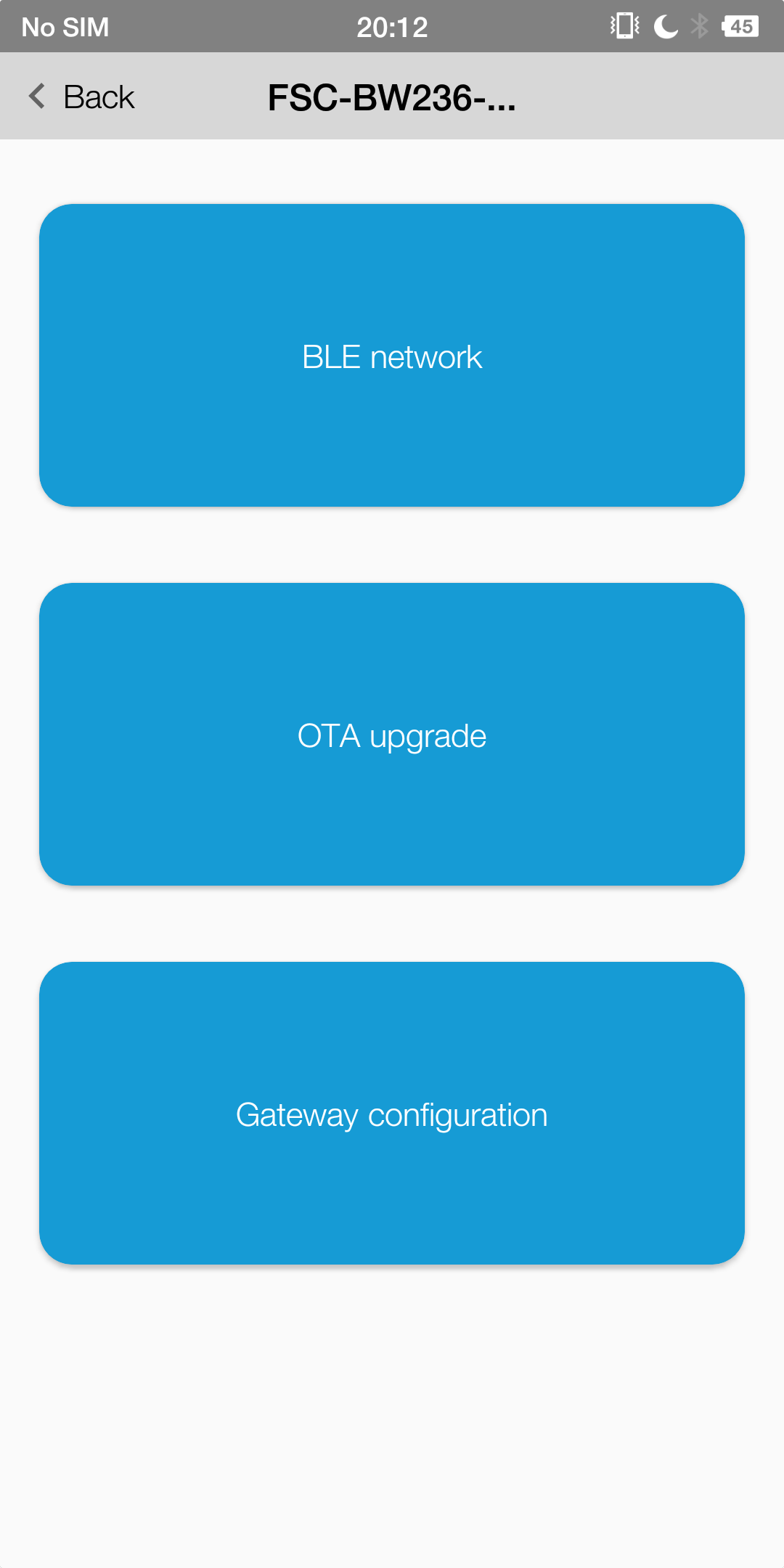
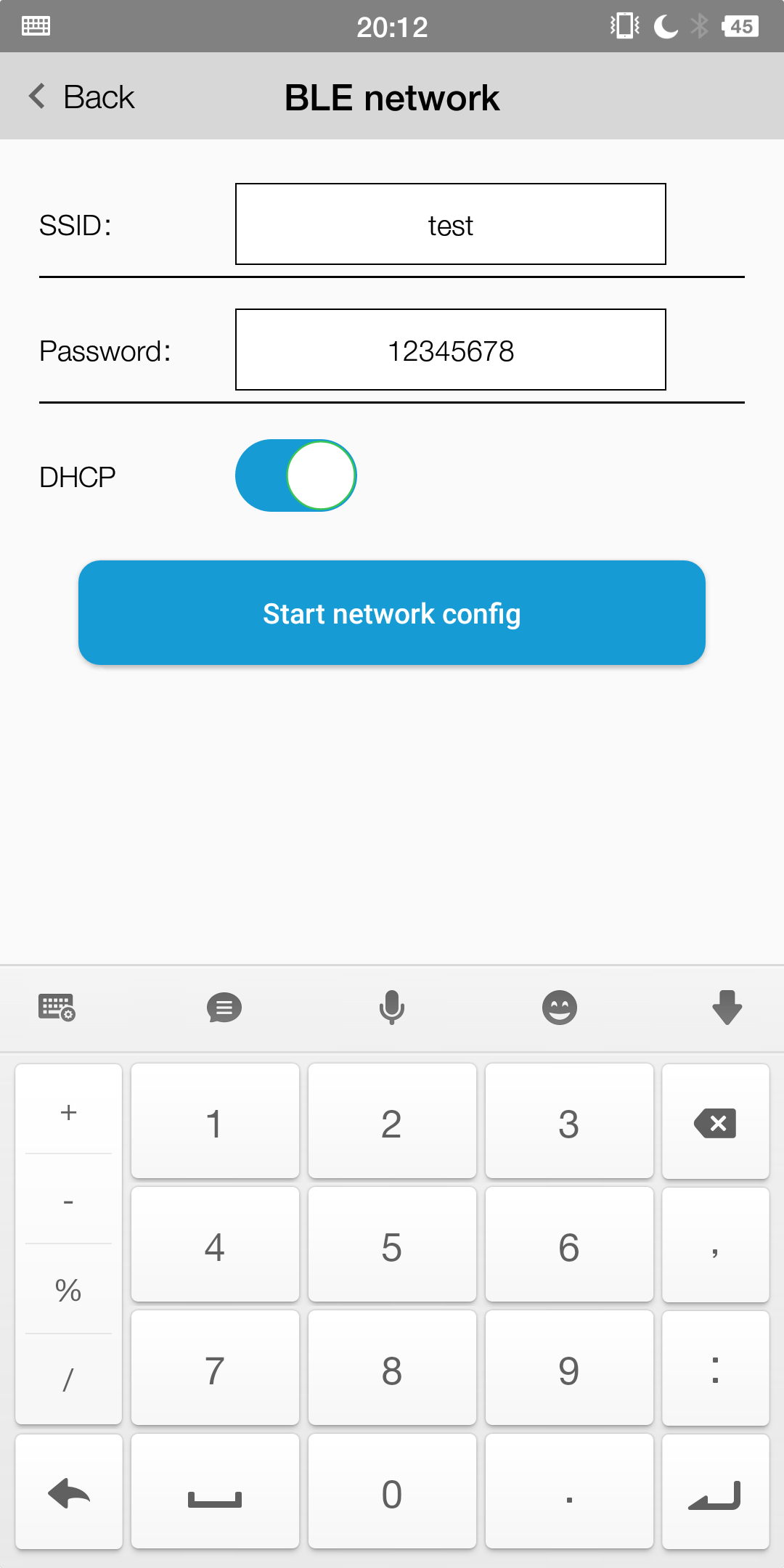
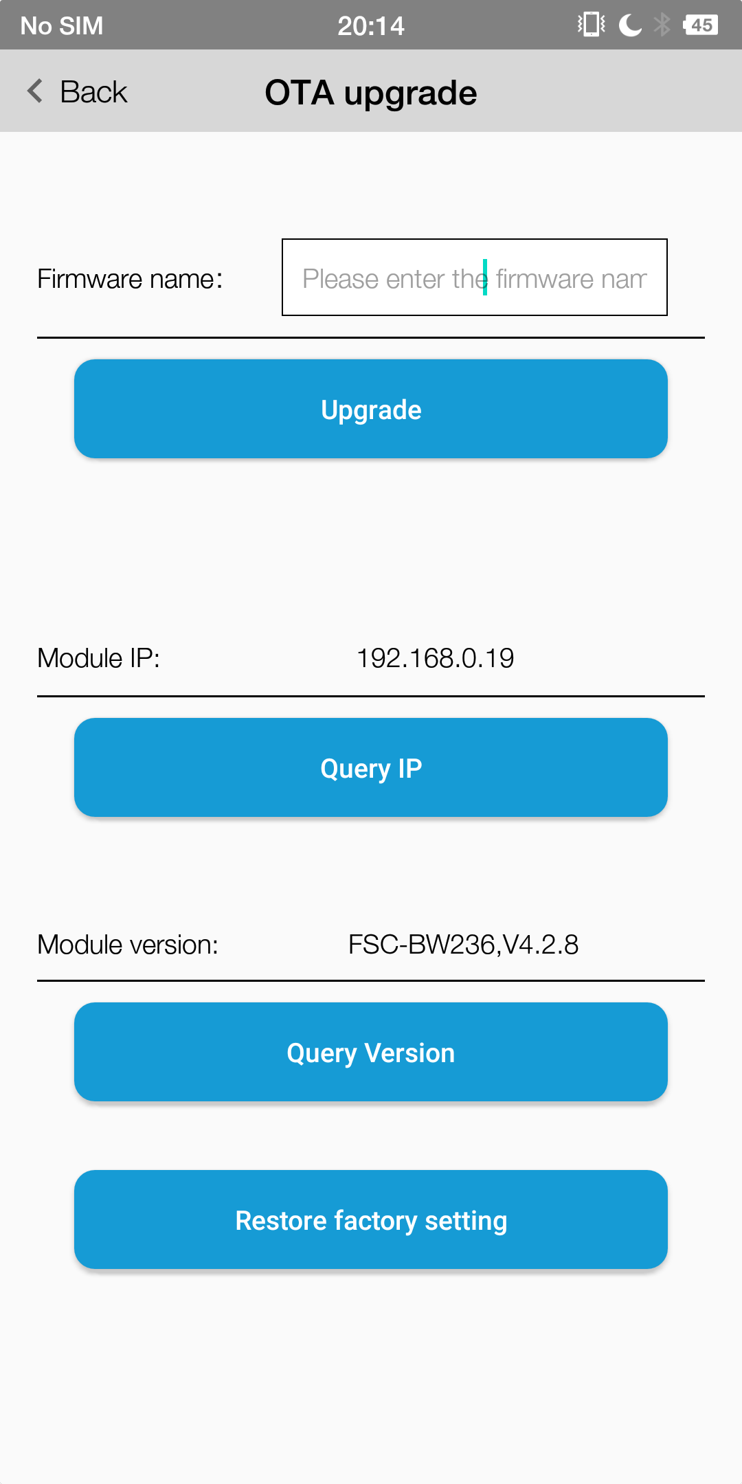
Note
Module needs to access the Internet,otherwise it will fail