FSC-BW256 Programming user guide
Introduction
Description
This design guide is intended for engineers developing BW256 Wi-Fi SoC modules
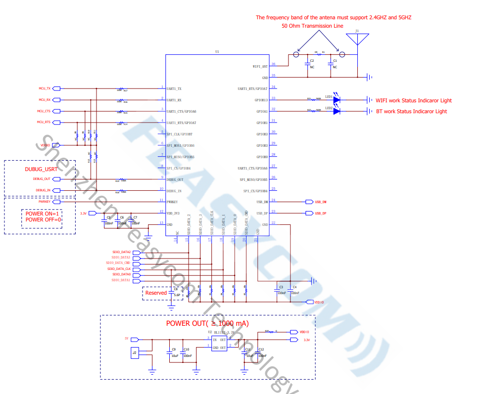
Hardware description
Pin diagram
Pin Description
Pin |
Pin Name |
Type |
Pin Descriptions |
|---|---|---|---|
1 |
UART_TX |
O |
Serial port TX |
2 |
UART_RX |
I |
Serial port RX |
3 |
UART_CTS |
I |
Serial port flow control pin(High effective) |
4 |
UART_RTS |
O |
Serial port flow control pin(High effective) |
9 |
UART_LOG_OUT |
O |
Module debugging serial port TX |
10 |
UART_LOG_IN |
I |
Module debugging serial port RX |
11 |
Pwrkey |
I/O |
power key |
12 |
VDD_3V3 |
VDD |
3.3V power supply |
13 |
GND |
VSS |
Ground connection |
21 |
GND |
VSS |
Ground connection |
22 |
GND |
VSS |
Ground connection |
32 |
LED0 |
I/O |
Bluetooth is connected to output high |
33 |
LED1 |
I/O |
Wi-Fi is connected to output high level |
35 |
GND |
VSS |
Ground connection |
36 |
EXT_ANT |
ANT |
antenna |
Hardware Design Notes
Simple module testing only needs to connect VDD/GND/UART_RX/UART_TX
The programming manual provides only a simple description of the IO port. For more detailed instructions and precautions, please refer to the design document
After drawing the schematic, please send it to Feiyitong for review to avoid the Bluetooth or Wi-Fi distance is not optimal
Hardware interface
GPIO
PWM
UART
SPI SLAVE
I2S Master/Slave
Analog Input/Output
Support Bluetooth protocol
SPP Client (Serial Port Profile)
SPP Server (Serial Port Profile)
GATT Server (Generic Attribute Profile)
Supports the Wi-Fi protocol
TCP (Transmisson Control Protocol)
UDP (USER Datagram Protocol)
HTTP (Hypertext Transfer Protocol)
MQTT (Message Queuing Telemetry Transport)
WEBSOCKET
Module default parameter
Wi-Fi default Settings
Wi-Fi Mode |
STA Mode |
Local AP SSID |
FSC-BW256-AP |
Local AP Password |
12345678 |
Local AP IP Address |
192.168.1.1 |
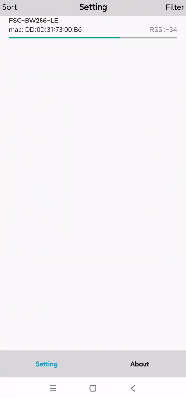
Bluetooth default Settings
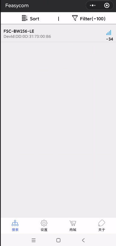
BLE Name |
FSC-BW256-LE |
BLE Mode |
LE-Peripheral |
SPP Name |
FSC-BW256 |
SPP PAIRCODE |
0000 |
Serial port default Settings
Baudrate |
921600bps |
Data Bits |
8 |
Parity |
None |
Stop Bits |
1 |
Commands Table
Specification
Applies to the entire document
{} : Content between {} is optional
<< : Content behind << represents a COMMAND from Host
>> : Content behind >> represents a RESPONSE/EVENT to Host
Instruction format
All commands start with “AT”, end with <CR><LF>
<CR> means “carriage return”, corresponds to hex value 0x0D
<LF> means “line feed”, corresponds to hex value 0x0A
If Command has Parameter, Parameter follows behind ‘=’
If Command has multiple Parameters, Parameter must be separated by ‘,’
If Command has Response, Response starts with <CR><LF>, ends with <CR><LF>
Module will always report command’s execution result by using OK for success or ERR<code> for failure
Error Code |
Meaning |
|---|---|
001 |
Failed |
002 |
Invalid parameter |
003 |
Invalid state |
004 |
Command mismatch |
005 |
Busy |
006 |
Command not supported |
007 |
Profile not turned on |
008 |
No memory |
Others |
Reserved for future use |
Event format
All events start with <CR><LF> and end with <CR><LF>
If the event contains parameters, the parameters should come after “=”
If the event contains multiple parameters, the parameters should be split with “,”
General Commands
AT - Serial port test instruction
Command |
AT |
Response |
OK |
Description |
Use the AT command to test whether the serial communication is normal |
AT+VER - Read Firmware Version
Command |
AT+VER |
Response |
+VER=Param1,Param2 |
|
Module type |
|
Firmware version |
AT+BAUD - Read/Write UART Baudrate
Command |
AT+BAUD{=Param} |
|
2400/4800/9600/19200/38400/57600/115200/128000/
230400/256000/460800/512000/921600/1000000/1382400
2000000/3000000/3250000
|
Response |
+BAUD=Param |
|
Returns the currently set baud rate |
AT+TPMODE - Read/Write Throughput Mode
Command |
AT+TPMODE{=Param} |
|
1:Enable transparent transmission mode
0:Disable transparent transmission mode
|
Response |
+TPMODE=Param |
|
Return to the current transparent transmission mode settings |
Description |
When the transparent transmission mode is enabled and a TCP, GATT or other connections are established, the serial port of the module will output the original data received from the remote end, and the data received by the serial port of the module will also be directly sent to the remote end.
When the transparent transmission mode is turned off, the serial port of the module will only process the received data in any state, and the data received by the module from the remote end will be output in command format from the serial port.
|
AT+REBOOT - Software Reset
Command |
AT+REBOOT |
Response |
OK |
Description |
The module releases all connections to the remote device and then restarts |
AT+RESTORE - Restore Factory Setting
Command |
AT+RESTORE |
Response |
OK |
Description |
Module restore all factory settings then reboot |
AT+STAT - Read Connection Status
Command |
AT+STAT |
Response |
+STAT=Param1, Param2, Param3, Param4, Param5, Param6, Param7 |
|
Connection Status in BLE Peripheral Mode |
|
Connection Status in BLE Central Mode |
|
Connection Status to Access Point |
|
Connection Status as Tcp Server |
|
Connection Status as Tcp Client |
|
Connection Status as SSL client |
|
Connection Status as MQTT client |
Description |
0: uninitialized
1: ready
2: connecting
3: connected
|
AT+NAME - Read/Write Bluetooth BR/EDR name
Command |
AT+NAME{=Param1{,Param2}} |
|
BR/EDR Bluetooth name(1~25 Bytes ASCII) |
|
MAC address suffix(0/1,default:1)
0-Disable suffix
1-Enable suffix “-XXXX” (lower 4 bytes of MAC address) after local name
|
Response |
+NAME=Param |
Description |
Set the Bluetooth name if there is a parameter, otherwise just read |
AT+LENAME - Read/Write Bluetooth BLE Name
Command |
AT+NAME{=Param1{,Param2}} |
|
BR/EDR Bluetooth name(1~25 Bytes ASCII) |
|
MAC address suffix(0/1,default:1)
0-Disable suffix
1-Enable suffix “-XXXX” (lower 4 bytes of MAC address) after local name
|
Response |
+NAME=Param |
Description |
Set the Bluetooth name if there is a parameter, otherwise just read |
AT+DSCA - Disconnect WIFi or Bluetooth connection
Command |
AT+DSCA |
Response |
OK |
Description |
The module is disconnected from Wifi or Bluetooth |
SPP Command
AT+ADDR-Read Bluetooth BR/EDR MAC
Command |
AT+ADDR |
Response |
+ADDR=Param |
|
MAC address of the module Bluetooth BR/EDR(12 Bytes ASCII) |
Description |
Only Read Supported |
AT+SPPSTAT-Read the SPP status
Command |
AT+SPPSTAT |
Response |
+SPPSTAT=Param |
|
0:Uninitialized
1:Read
2:Connecting
3:Connected
|
Description |
Example Query the SPP connection status |
AT+SPPDISC-Disconnects the SPP
Command |
AT+SPPDISC |
Response |
OK |
Description |
Disconnects the current SPP connection to the remote device |
AT+SPPSEND-Sends SPP data
Command |
AT+SPPSEND=Param1,Param2 |
|
Length of data to be sent |
|
The content of the data to be sent |
Response |
OK:Send complete
ERR002:The parameter or format is incorrect
ERR003:Bluetooth connection failed
|
Description |
The data length should be less than 1000 |
AT+SSP-Query/modify the BT pairing mode
Command |
AT+SSP{=Param} |
|
0: Easy pairing mode (default)
1:Pairing code mode
|
Response |
OK
|
Description |
AT+PIN - Read/Write Bluetooth BLE PIN Code
Command |
AT+PIN{=Param} |
|
pairing code
|
Response |
OK
|
Description |
The default pairing code is 0000. The value contains a maximum of 15 characters and is valid only in pairing code mode, that is, SSP=1
|
AT+COD - Read/Write the BT device type
Command |
AT+COD{=Param} |
|
Device type (hexadecimal)
|
Response |
OK
|
Description |
Default printer (0x680) |
BLE Command
AT+LEADDR - Read the Bluetooth BLE MAC
Command |
AT+LEADDR |
Response |
+LEADDR=Param |
|
Module’s LE MAC address (12 Bytes ASCII) |
Description |
Only Read Supported |
AT+GATTSEND - Send BLE Data in Peripheral Mode
Command |
AT+GATTSEND=Param1,Param2 |
|
Payload length (1~999) |
|
Payload (1~999 Bytes UTF8) |
Response |
OK:Send complete
ERR002:The parameter or format is incorrect
ERR003:The Bluetooth connection is down
|
Description |
The data length should be less than 1000 |
AT+GATTSTAT - Read the BLE connection status
Command |
AT+GATTSTAT |
Response |
+GATTSTAT=Param
|
|
0: uninitialized
1: ready
2: connecting
3: connected
|
Description |
Wi-Fi Command
AT+ROLE - Read/Write Wi-Fi Mode
Command |
AT+ROLE{=Param} |
|
1: STA mode
2: AP mode
|
Response |
+ROLE=Param
|
Description |
Module will reboot after setting |
AT+SCAN - Scan Devices
Command |
AT+SCAN=5(scan for surrounding hot spots) |
Response |
+SCAN=Param1,Param2,Param3,Param4,Param5,Param6 |
|
Scan serial number |
|
has a fixed value of 5, indicating the scanning hotspot |
|
Address code of the hotspot |
|
Indicates the signal value between the module and the hotspot |
|
Channels |
|
Indicates the hotspot name |
Description |
AT+RAP - Read Connected AP’s information/Connect to Remote AP
Command |
AT+RAP=<Param1>,<Param2>
|
|
AP’s SSID |
|
AP’s password,if way of encryption is OPEN, no need to set this parameter |
Response |
OK |
Description |
1. This command needs to be sent in STA mode or coexistence mode, that is, +ROLE=1 or 3
2. The module uses WPA2 encryption to connect to the hotspot by default
3. To connect to the hotspot whose encryption mode is OPEN, set the first parameter, for example
AT+RAP=Feasycom
4. Send AT+RAP to query the hotspot name
|
AT+LIP - Read Current Local IP Address
Command |
AT+LIP |
Response |
+LIP=Param |
|
IP address |
Description |
When the module successfully connects to the hotspot, it will get an IP address, otherwise “0.0.0.0” is returned |
AT+MDNSEN - Enable/Disable MDNS Function
Command |
AT+MDNSEN{=Param} |
|
0:Disable(default)
1:Enables
|
Response |
+MDNSEN=Param |
AT+DHCP - Read/Write IP Distribution Mode
Command |
AT+DHCP{=Param} |
|
0:Use static IP
1:Use dynamic IP(default)
|
Response |
+DHCP=Param |
Description |
If a static IP address is used for connection, ensure that the static IP address, mask, gateway, and DNS Settings are correct.
Otherwise, network communication may be interrupted
|
AT+SIP - Read/Write Static IP
Command |
AT+SIP{=Param} |
|
IPV4 Address |
Response |
+SIP=Param |
Description |
This command can be used when +DHCP=0 |
AT+GW - Read/Write Gateway
Command |
AT+GW{=Param} |
|
IPV4 Address |
Response |
+GW=Param |
Description |
This command can be used when +DHCP=0 |
AT+MASK - Read/Write Subnet Mask
Command |
AT+MASK{=Param} |
|
IPV4 Address |
Response |
+MASK=Param |
Description |
This command can be used when +DHCP=0 |
AT+DNS - Read/Write DNS Address
Command |
AT+DNS{=Param} |
|
IPV4 Address |
Response |
+DNS=Param |
Description |
This command can be used when +DHCP=0 |
AT+LHNAME - Read/Write the STA name
Command |
AT+LHNAME{=Param} |
|
Device name (up to 32 bytes) |
Response |
+LHNAME=Param |
Description |
FSC-BW256(Default) |
AT+APAC - Read/Write Automatically Connect to AP
Command |
AT+APAC{=Param} |
|
0:Disable
1:Enable(default)
|
Response |
+APAC=Param |
Description |
This command can be used when +ROLE=1 or 3 |
AT+RSSI - Read Signal Strength Between Module And AP
Command |
AT+RSSI |
Response |
+RSSI=Param |
|
RSSI value (-99 ~ 0) |
Description |
The result of RSSI is 0 when disconnect from AP. |
AT+MAC - Read Wi-Fi MAC Address
Command |
AT+MAC |
Response |
+MAC=Param |
|
Wi-Fi MAC Address(12 Bytes ASCII) |
Description |
MAC address can only be read , not be written |
AT+APINFO - Read information about connected AP
Command |
AT+APINFO |
Response |
+APINFO=Param1,Param2,Param3,Param4 |
|
AP MAC address (12 Bytes ASCII) |
|
1:5G
0:2.4G
|
|
The frequency band of AP |
|
Indicates the SSID of AP |
Description |
Read can only be made if the hotspot is connected |
AT+LAP - Read/Write AP Mode Configuration
Command |
AT+LAP{=Param1,Param2,Param3} |
|
The SSID of the module as a AP |
|
The password of the module as a AP |
|
The IP address of the module as a AP |
Response |
+LAP=Param1, Param2, Param3 |
Description |
If the module is configured as a AP with OPEN encryption,
no need to set the Param2,
such as AT+LAP=FSC-BW236-AP,192.168.1.1
|
AT+CHANNEL - Read/Write the AP mode channel
Command |
AT+CHANNEL{=Param} |
|
module as a channel in AP mode |
Response |
+CHANNEL=Param |
Description |
Module will decide whether to turn on 2.4G or 5G hotspot based on channel selection |
AT+WLANC - Start SOCKET/MQTT/WEBSOCKET
Command |
AT+WLANC=Param |
|
3:Enable TCP/UDP/SSL
4:Connect to MQTT or cloud platform
5:Starts the WEBSOCKET
|
Response |
OK |
Description |
This command can only be used after the SOCKET or MQTT configuration is completed |
TCP/UDP Command
AT+SOCK - Read/Write SOCKET
Command |
AT+SOCK{=Param1,Param2,Param3,
Param4}
|
|
Protocol Type(TCPS,TCPC,UDP,SSL) |
|
Port of Module |
|
Remote Address |
|
Remote Port |
Response |
+SOCK=Param1, Param2, Param3, Param4 |
Description |
The TCP SERVER is enabled after power on, default port is 9100
Param3 and Param4 can be omitted if module works as a TCP Server or a UDP
|
AT+WFSEND - Sends SOCKET data to the remote device
Command |
AT+WFSEND=Param1,Param2,Param3 |
|
Indicates the ID of the TCP/UDP connection |
|
Send data length (not more than 1460 bytes) |
|
Sends data content |
Response |
OK |
Description |
When the module functions as the TCP server, it can be connected by a maximum of three remote clients by default. The ids of the three remote clients are 0, 1, and 2 respectively;
When a module functions as a TCP client, the communication ID is 3 by default;
When UDP is enabled on the module, the communication ID is 4 by default.
|
AT+CLOSE - Close Connection as TCP client
Command |
AT+CLOSE |
Response |
OK |
Description |
This command can be used to disconnect from a remote TCP Server,if module works as a TCP Client |
AT+IDLETO - Read/Write the automatic disconnection time of TCP Server short connections without data
Command |
AT+IDLETO{=Param} |
|
Short connection Duration of automatic disconnection without data (unit s, default is 0, that is, long connection) |
Response |
OK |
Description |
AT+BRDDATA - Read/Write UDP broadcast data
Command |
AT+BRDDATA{=Param1,Param2,Param3} |
|
UDP broadcast port |
|
UDP broadcast interval (unit s) |
|
UDP Broadcast content (up to 128 bytes) |
Response |
OK |
Description |
AT+BRDEN - Read/Write the UDP broadcast switch
Command |
AT+BRDEN{=Param} |
|
0: Disables UDP broadcast,
1: Enables UDP broadcast
|
Response |
OK |
Description |
HTTP Command
AT+HTTP - Access the HTTP server
Command |
AT+HTTP=Param1,Param2,Param3{,Param4} |
|
HTTP Request Method, only support GET and POST |
|
HTTP server’s address |
|
HTTP server’s URI |
|
Resume breakpoint to support
This Parameter can be omitted.
Format is “Range:bytes=starting byte-ending byte”
|
Response |
OK |
Description |
AT+HTTP Used to access the HTTP server. If you need to access the HTTPS server, use the AT+HTTPS command instead
The default port for accessing the HTTP server is 80, and the default port for accessing the HTTPS server is 443. If you want to change the port, specify the port following the server address. For example, if the specified port is 778, 192.168.0.179:778 can be used
|
Note
“http://httpbin.org” is available for testing HTTP
MQTT Command
AT+BROKER - Read/Write MQTT broker
Command |
AT+BROKER{=Param} |
|
MQTT server address |
Response |
+BROKER=Param |
Description |
“gpssensor.ddns.net” is available for testing MQTT |
AT+CLIENTID - Read/Write MQTT Client ID
Command |
AT+CLIENTID{=Param} |
|
MQTT Client ID |
Response |
+CLIENTID=Param |
AT+USERNAME - Read/Write MQTT USERNAME
Command |
AT+USERNAME{=Param} |
|
MQTT USERNAME |
Response |
+USERNAME=Param |
AT+MQTTPWD - Read/Write MQTT password
Command |
AT+MQTTPWD{=Param} |
|
MQTT MQTTPWD |
Response |
+MQTTPWD=Param |
AT+SUBTPC - Read/Subscribe MQTT Topic
Command |
AT+SUBTPC{=Param1,Param2} |
|
Topic |
|
QOS, only can be 0,1,2 |
Response |
+SUBTPC=Param1,Param2 |
Note
This command returns an error if you repeatedly subscribe to the TOPIC with the same name
Currently, you can subscribe to a maximum of 5 different topics. If you do not meet the usage requirements, you are advised to use wildcard characters in actual use
AT+UNSUBTPC - Unsubscribe Specify MQTT Topic
Command |
AT+UNSUBTPC=Param |
|
Specify the topic to be unsubscribed |
Response |
OK |
Description |
There is no need to specify a QoS value when unsubscribes |
AT+UNSUBALL - Unsubscribe from all MQTT topics
Command |
AT+UNSUBALL |
Response |
OK |
AT+MQTTSEND - Send MQTT Data
Command |
AT+MQTTSEND=Param1,Param2,Param3,Param4 |
|
Publish Topic |
|
QOS(0,1,2) |
|
Payload length |
|
Payload |
Response |
OK |
AT+MQTTMODE - Read/Write MQTT Mode
Command |
AT+MQTTMODE{=Param} |
|
0: Connect to general MQTT Server(default)
1: Connect to Ali Cloud Platform
2: Connect to QCloud Platform(Tencent)
|
Response |
OK |
Description |
Module connects to different cloud platforms by switching MQTT modes |
AT+MQTTPORT - Read/Write MQTT Port
Command |
AT+MQTTPORT{=Param} |
|
MQTT port, default is 1883 |
Response |
+MQTTPORT=Param |
Description |
Based on the actual server port |
AT+MQTTKAI - Read/Write MQTT Keepalive
Command |
AT+MQTTKAI{=Param} |
|
MQTT Keepalive time:uint is second,default value is 60 |
Response |
+MQTTKAI=Param |
Note
Set the value based on the actual platform usage restrictions.
General platforms, such as Alicloud, require an MQTT keepalive period of 30 to 1200 seconds
If module is disconnected unexpectedly more than {keepalive period * 1.5}, the MQTT server will automatically disconnect module
Firmware Upgrade (Remote OTA)
AT+OTA - Remote OTA
Command |
AT+OTA=Param |
|
Name of the firmware to be upgraded |
Response |
OK |
Description |
The firmware name is provided by feasycom engineering or technical support team members.
The module will return $OTA=1 after a successful upgrade
|
Note
Do not operate other commands or functions during the upgrade. Otherwise, the upgrade may fail or cause unexpected situations
Events Table
MQTT Indication
+MQTTSTAT - MQTT Status
Format |
+MQTTSTAT=Param |
|
(0) uninitialized
(1) ready
(2) connecting
(3) connected
|
+MQTTDATA - MQTT Received Data
Format |
+MQTTDATA=Param1,Param2,Param3 |
|
Topic |
|
Payload length |
|
Payload |
SOCKET Indication
+WFDATA - Receive SOCKET Data
Format |
+WFDATA=Param1,Param2,Param3 |
|
TCP/UDP Connection ID |
|
Payload length |
|
Payload |
Note
For details about the connection ID, see the AT+WFSEND command
GATT Indication
+GATTSTAT - GATT Status
Format |
+GATTSTAT=Param |
|
(0) uninitialized
(1) ready
(2) connecting
(3) connected
|
+GATTDATA - Receive GATT Data
Format |
+GATTDATA=Param1,Param2 |
|
Payload length |
|
Payload |
SPP indication
+SPPSTAT - SPP status
Format |
+SPPSTAT=Param |
|
(0) Uninitialized
(1) No connection
(2) Connecting
(3) Connected
|
+SPPDATA - SPP receives data
Format |
+SPPDATA=Param1,Param2 |
|
Payload length |
|
Payload |
Application Scenarios
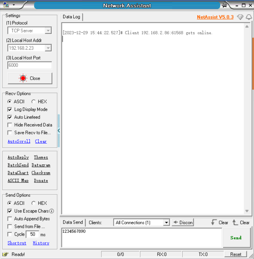
TCP Server Application
Note
Note: To use transparent data transmission, send AT+TPMODE=1 before setting the Wi-Fi mode
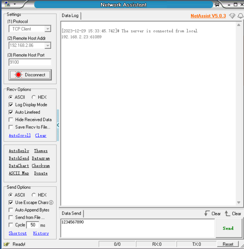
TCP Client Application
Note
Note: To use transparent data transmission, send AT+TPMODE=1 before setting the Wi-Fi mode
UDP application
Note
Note: To use transparent data transmission, send AT+TPMODE=1 before setting the Wi-Fi mode
MQTT Application
Switch Throughput Mode to Command Mode
Note
The above data format is different from the normal AT command which ends with <CR><LF>
The above data does not have any terminator attached
Network Configuration and OTA
OTA by AT Command
Note
The firmware is stored in the specific server and the upgrade mode can be changed as required by customers
Module needs to access the Internet,otherwise it will fail
OTA by FeasyWiFi APP
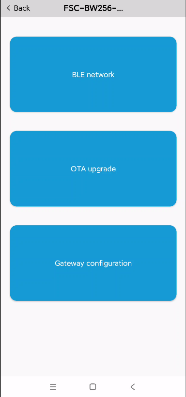
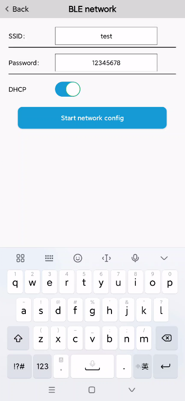
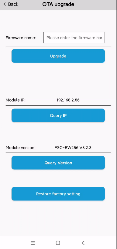
Note
The hotspot needs to support access to the Internet.
Wechat mini program distribution network and OTA usage instructions
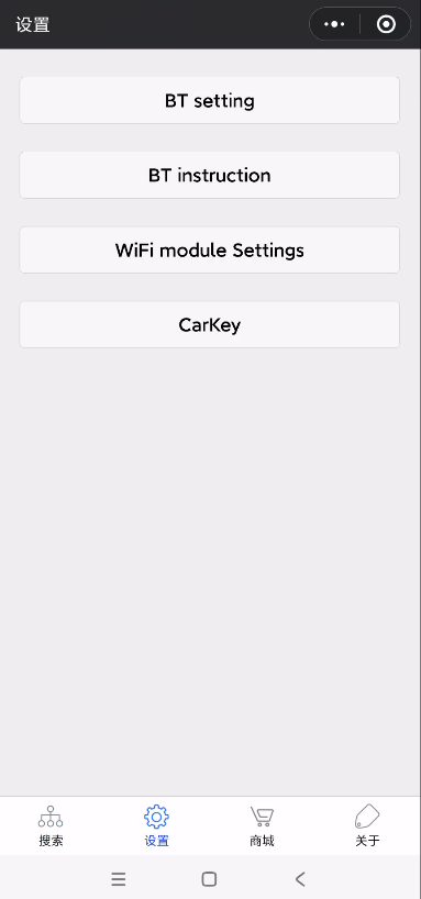
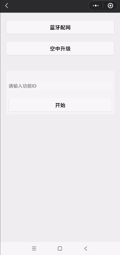
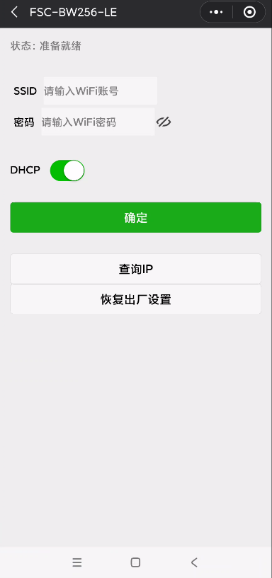
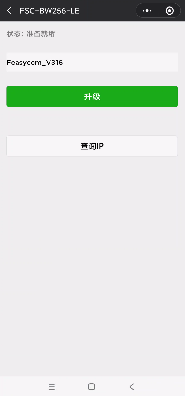
Note
The hotspot needs to support access to the Internet.