FSC-BT691 user guide
Introduction
Description
This design guide is suitable for engineers developing FSC-BT691 series Bluetooth modules
Module Default Settings
Name |
Feasycom |
Service UUID |
FFF0 |
Write UUID |
FFF2 |
Notify UUID |
FFF1 |
UART Baudrate |
115200/8/N/1 |
Hardware Description
Pin Diagram
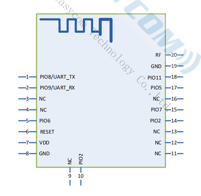
Pin Description
Pin |
Pin Name |
Type |
Pin Descriptions |
|---|---|---|---|
1 |
UART_TX |
O |
UART data output |
2 |
UART_RX |
I |
UART data input |
6 |
MODE |
I |
L=throughput mode ,H=command mode |
6 |
RESET |
I |
External reset input: Active LOW, with an inter an internal pull-up. |
7 |
VDD |
Power |
Power supply voltage 3.3V, LDO power supply preferred |
8 |
GND |
GND |
GND |
15 |
DISCONNECT |
I |
High-level disconnect (must be connected first) |
17 |
LED |
O |
Bluetooth not connected output square wave, Bluetooth connection output high level |
18 |
STATUS |
O |
Bluetooth not connected output low level, Bluetooth connection output high level |
20 |
EXT_ANT |
ANT |
Changing the 0 ohm resistance near the antenna, it is possible to connect a Bluetooth antenna externally |
Hardware Design Notes
The simple test of the module only needs to connect VDD/GND/UART_RX/UART_TX to use
If the MCU needs to obtain the connection status of the Bluetooth module, it needs to be connected to the STATUS pin
After drawing the schematic diagram, please send it to Feasycom for review, so as to prevent the Bluetooth distance from not reaching the best effect
Function Description
GPIO state
MODE PIN is PIN 6
State |
Description |
|---|---|
Low level |
Throughput mode |
High level |
AT command mode |
Note
To use this function, the pin function needs to be enabled using the AT command. Please refer to AT+PIOCFG for more details.
DISCONNECT PIN is PIN 15
tate |
Description |
|---|---|
Low level |
– |
High level |
disconnected |
Note
To use this function, the pin function needs to be enabled using the AT command. Please refer to AT+PIOCFG for more details.
LED PIN is PIN 17
State |
Description |
|---|---|
1Hz square wave |
disconnect state |
high level |
connected state |
Connection status PIN is PIN 18
State |
Description |
|---|---|
low level |
disconnect state |
high level |
connected state |
Mode
Throughput mode |
when disconnected, the data received by the serial port is analyzed according to the AT command;
when connected, all the data received by the serial port is sent to the remote Bluetooth as it is.
|
Command mode |
when disconnected, the data received by the serial port is analyzed according to the AT command;
when connected, The data received by the serial port is still parsed according to the AT command.
when it is necessary to send data to the remote end, send AT+LESEND command.
|
GATT Throughput Service
type |
UUID |
Permissions |
Description |
Service |
0xFFF0 |
GATT Throughput Service |
|
Write |
0xFFF2 |
Write,Write Without Response |
APP send data to module |
Notify |
0xFFF1 |
Notify |
Module send data to remote |
AT command description
Command description
Throughout this specification:
Content between { } is optional
Content behind << represents a COMMAND from Host
Content behind >> represents a RESPONSE/EVENT to Host
Command
Command Format
All commands start with AT, end with <CR><LF>
<CR> means “carriage return”, corresponds to hex value 0x0D
<LF> means “line feed”, corresponds to hex value 0x0A
If Command has Parameter, Parameter follows behind ‘=’
If Command has multiple Parameters, Parameter must be separated by ‘,’
If Command has Response, Response starts with <CR><LF>, ends with <CR><LF>
The module should always return the result of instruction execution (success returns OK,failure returns ERROR)
Event
Event Format
All Events start with <CR><LF>, end with <CR><LF>
If Event has Parameter, Parameter follow behind ‘=’
If Event has multiple Parameters, Parameter must be separated by ‘,’
Commands Table
AT - Serial communication test
Command |
AT |
Response |
OK |
Description |
When powering on or changing the baud rate, test the UART communication between the host and the module |
AT+VER - Get Firmware Version
Command |
AT+VER |
Response |
+VER=Param |
|
Firmware version |
Description |
Get Firmware Version |
AT+ADDR - Get MAC Address
Command |
AT+ADDR |
Response |
+ADDR=Param |
|
Module’s MAC address (12 Bytes ASCII) |
Description |
Get MAC Address |
AT+NAME - Get/Set Local Name
Command |
AT+NAME{=Param1{,Param2}} |
|
local name(1~29 Bytes ASCII) |
|
MAC address suffix(0/1,default:0)
0: Disable suffix
1: Enable suffix “XXXX” (lower 4 bytes of MAC address) after local name
|
Response |
+NAME=Param |
|
local name |
Description |
Write local name if parameter exist, otherwise read current local name |
AT+BAUD - Get/Set Uart Baudrate
Command |
AT+BAUD{=Param} |
|
baudrate(2400/4800/9600/14400/19200/28800/38400/
57600/115200/230400/460800/500000/921600/1000000,
default:115200)
|
Response |
+BAUD=Param |
|
baudrate |
Description |
Module will change baudrate to target value immediately |
AT+TXPOWER - Get/Set TX Power
Command |
AT+TXPOWER{=Param} |
|
tx power(default:3) |
Response |
+TXPOWER=Param |
|
tx power |
Description |
Get/Set TX Power |
AT+LPM - Get/Set low power config
Command |
AT+LPM{=Param} |
|
low power mode (0/1, default: 0)
0: disable
1: enable low power and wake up by UART
|
Response |
+LPM=Param |
|
low power mode |
Description |
Get/Set low power config |
AT+ADVIN - Get/Set advertising interval
Command |
AT+ADVIN{=Param} |
|
advertising interval (100~10000 ms0 ms, 默认: 687ms) |
Response |
+ADVIN=Param |
|
advertising interval |
Description |
Get/Set advertising interval |
AT+DISC - Disconnect specified connection
Command |
AT+DISC |
Response |
OK |
Description |
disconnect Bluetooth connection |
AT+LECCONN - Initiate a connection to the specified address
Command |
AT+LECCONN{=Param1{,Param2{,Param3{,Param4}}}} |
|
12-byte device address + 1-byte address type |
|
Communication Service UUID |
|
Communication UUID with write/write without rsp permission |
|
Communication UUID with notification permission |
Response |
OK |
Description |
Initiate a connection to the specified device, the parameter consists of 12 bytes (device address) and 1 byte
(address type), generally the address type is “0” or “1”. address
How to get the address type:
Send AT+SCAN=1 command, get parameter2. example:
+SCAN=0,0,DC0D30001ED4,-65,10,FSC-BT946
Connection command:
AT+LECCONN=DC0D30001ED40
|
AT+SCAN - SCAN for nearby devices
Command |
AT+SCAN{=Param1{, Param2{, Param3}}} |
|
scanning method(0~1)
0: stop scanning
1: Scan nearby devices, filter duplicate addresses, up to 8 devices can be found
|
|
Scan Timeout Setting(200ms~2s,100 is equal to 1000ms) |
|
Scan Filter Name/MAC (If it’s a 12-digit standardized MAC, filter by MAC; otherwise, filter by name) |
Response |
+SCAN=Param1,Param2,Param3,Param4,Param5
|
|
MAC Address type (1 byte) |
|
MAC address (12 bytes) |
|
RSSI |
|
Device name length |
|
Device name |
Description |
AT+SCAN=1 Commonly used for searching before connecting
|
AT+TPMODE - Get/Set throughput mode
Command |
AT+TPMODE{=Param} |
|
Mode(0~1,default 1)
0: Command Mode
1: Throughput Mode
|
Response |
+TPMODE=Param |
|
Mode |
Description |
Command Mode:
When bluetooth connected and in throughput mode,
the AT command will be de-active.
Throughput Mode:
every byte received via physical UART will be sent
to remote.
|
AT+ADVDATA - Get/Set advertising manufacturer specific data
Command |
AT+ADVDATA{=Param} |
|
manufacturer specific data, tag 0xff(len <= 25>) |
Response |
+ADVDATA=Param |
|
manufacturer specific data, tag 0xff |
Description |
Get/Set advertising manufacturer specific data |
AT+LESEND - Send data to remote device
Command |
AT+LESEND{=Param1,Param2} |
|
Connection index |
|
data |
Response |
OK |
Description |
Send data to remote device
|
AT+REBOOT - Soft Reboot
Command |
AT+REBOOT |
Response |
OK |
Description |
Module release all Bluetooth connections then reboot |
AT+RESTORE - Restore Factory Settings
Command |
AT+RESTORE |
Response |
OK |
Description |
Module restore all factory settings then reboot |
AT+PIOCFG - 开关引脚功能
Command |
AT+PIOCFG{=param1,param2} |
|
Enable/Disable the function of the mode selection pin(default : 0) | 0: Disable | 1: Enable |
|
Enable/Disable the disconnect pin function(default : 0) | 0: Disable | 1: Enable |
Response |
OK |
Description |
Query and modify pin function |
Event Table
+SCAN - AT+SCAN=1 Scan Result
Indication |
+SCAN=Param1,Param2,Param3,Param4,Param5,Param6 |
|
MAC address type (1 byte) |
|
MAC address (12 Bytes ASCII) |
|
RSSI |
|
remote device name len |
|
remote device name |
Description |
After the module receives AT+SCAN=1, it will continue to scan, and report through +SCAN after finding the device |
+GATTSTAT - GATT State
Indication |
+GATTSTAT=Param1,Param2 |
|
Connection Index |
|
GATT State (1~3)
1: Standby
2: Connecting
3: Connected
|
Description |
In the command mode, if the connection status of the module changes, it will be actively reported through +GATTSTAT |
+DATA - GATT Received Incoming Data
Indication |
+DATA=Param1,Param2,Param3 |
|
Payload length |
|
Payload |
Description |
In the throughput mode: report data without +DATA header
In the command mode: report data with +DATA header +DATA=1,5,12345
|
Application scenarios
Get/Set the default parameters of the module
When the module is disconnect state, it will parse the uart data according to the AT command. The host can get and set the default parameters of the module, as shown in the figure below:
Set the device name to ABC
Get device name
Get MAC address
Process of sending data
When the module is powered on, it will continue to send advertising data, and the remote device (mobile phone) can scan the advertising packet. And initiate a connection request to the module. After the connection is successful, the module will pull up the connection status pin to notify the host that the Bluetooth connection is successful. The host can send data to the remote device through the Bluetooth module, and the remote device can also send data to the host.
The module acts as the central to connect to the remote device
The module can be used as a master device to connect to the slave device, and the host can send commands to control the module to scan and connect and disconnect. The figure below shows the process of connecting other devices: