Feasycom WMK-KIT2(UWB) User Guide
Program Introduction - WMK-K2(UWB)
Feasycom Warehouse Management KIT2 - WMK-K2(UWB)
Plist
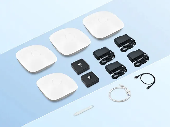
FSC-UP3312A&B |
4pcs |
Gateway |
FSC-UP3311 |
2pcs |
UWB Tags(internal battery) |
other 1 |
4pcs |
FSC-UP3312A&B adapter plug |
other 2 |
1pcs |
FSC-UP3311 battery shell opener |
other 3 |
1pcs |
RJ45 connecting line |
other 4 |
1pcs |
USB connecting line |
KIT Specifications
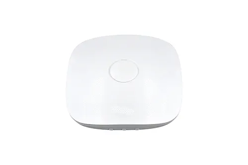
FSC-UP3312A/B | UWB Gateway specification
Note
Power supply via PoE or DC Notice:Make sure that the router or switch supports PoE power supply
UWB standard |
IEEE 802.15.4 & 802.15.4z |
Wi-Fi |
2.4G |
Radius of reception |
≥40m |
Accuracy |
≤40cm |
Power supply |
PoE or DC |
Installation technology |
Wall hanging or suction top |
FSC-UP3311 | UWB Tags specification
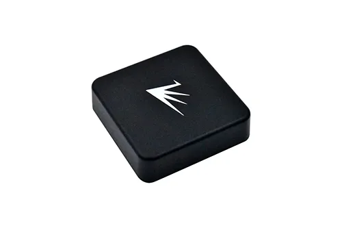
UWB standard |
IEEE 802.15.4 & 802.15.4z |
Wi-Fi |
2.4G |
Radius of reception |
≥40m |
Accuracy |
≤40cm |
Power supply |
2*AAA battery(Supports replaceable batteries) |
Installation technology |
Multiple |
Options |
IMU, Button, Vibration, Buzzer, NFC |
Application and device deployment
Application video
Application deployment diagram
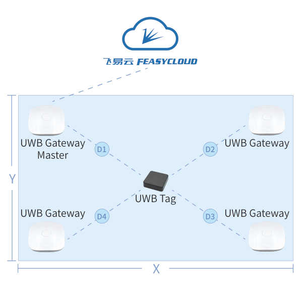
Deployment recommendations
An area needs to have 4 base station gateways
The gateway needs to be on the same plane as much as possible
The gateway needs to be more than 50 cm away from the wall
D1+D3 or D2+D4 should be less than the maximum receiving distance of the tag or gateway
How to boot a device
Working status indication
Indicator light Blue :Working properly
Indicator light Red :Set distribution mode (only for base station gateway)
Indicator light Flashing blue :Not working properly
Quick suite evaluation
Preparation for assessment
System Environment Requirements
Windows system :Windows10 or higher;
Google Chrome Ver :ver 112 or higher;
Feasycom Feasycloud.
Preparation of equipment
FSC-UP3312 Gateway ;
USB connecting line,PC;
Feasycloud has authorized login email account and password;
Internet-connected router WiFi or mobile phone to enable hotspot.
Feasycloud login
The following is based on Windows 10 and Google Chrom browser 119 operating environment to demonstrate the operation instructions:
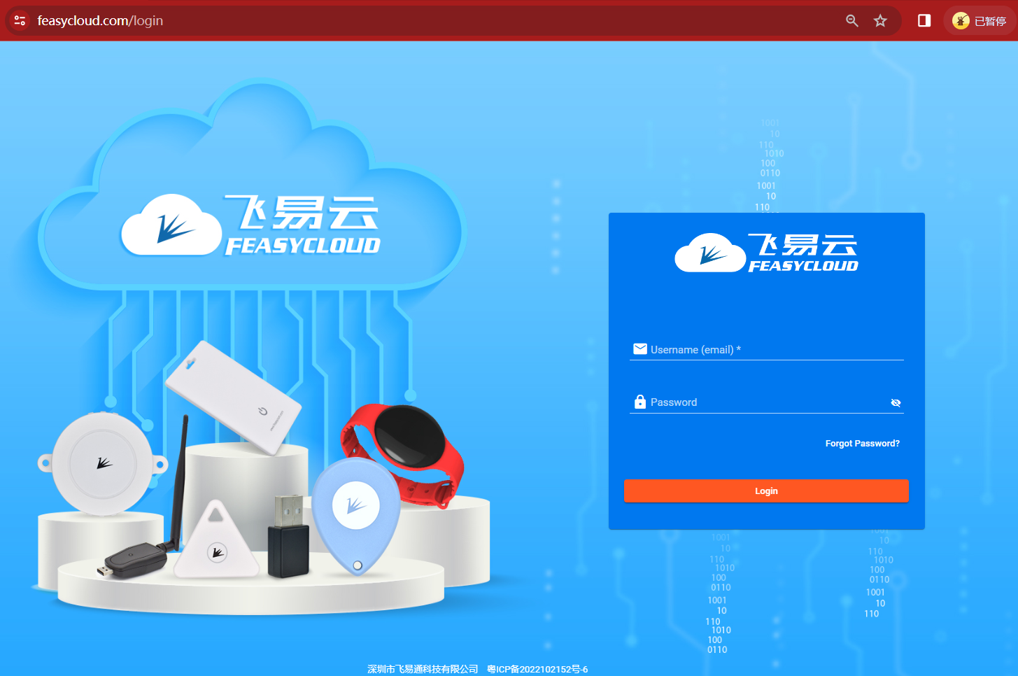
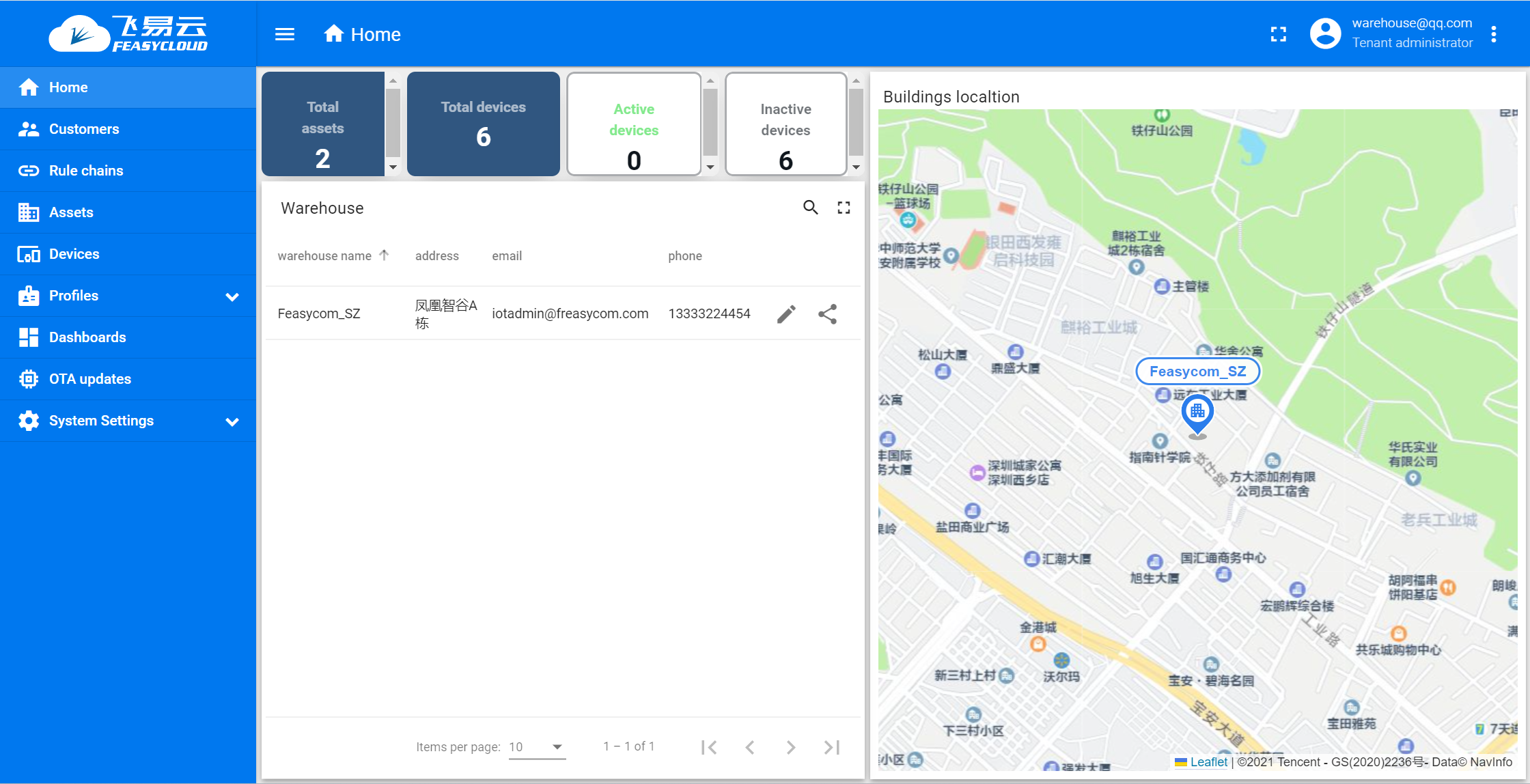
After you login successfully, you will enter the Home main page
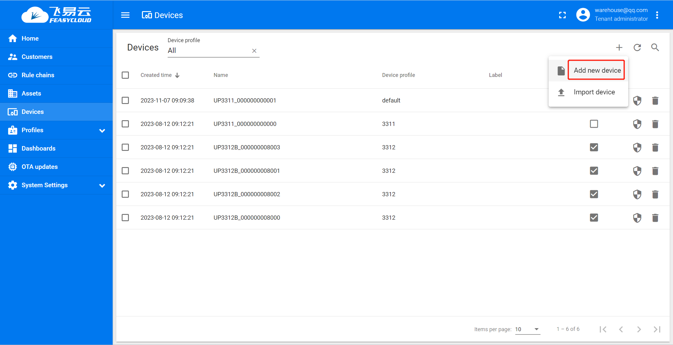
Add the base station gateway
Step 1. On the feasycloud_home, access the device configuration page through the Device in the left navigation menu. Click the Add New device button
Step 2. Device profile select 3312 and check as gateway.
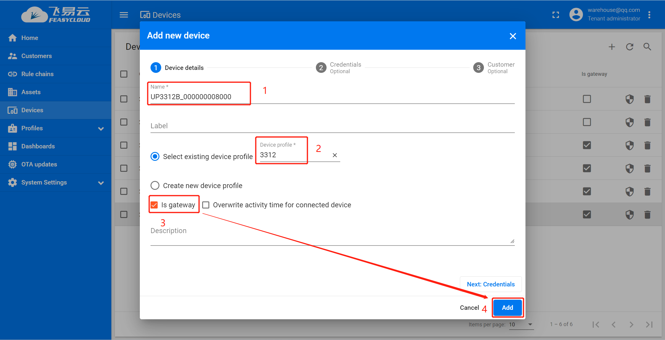
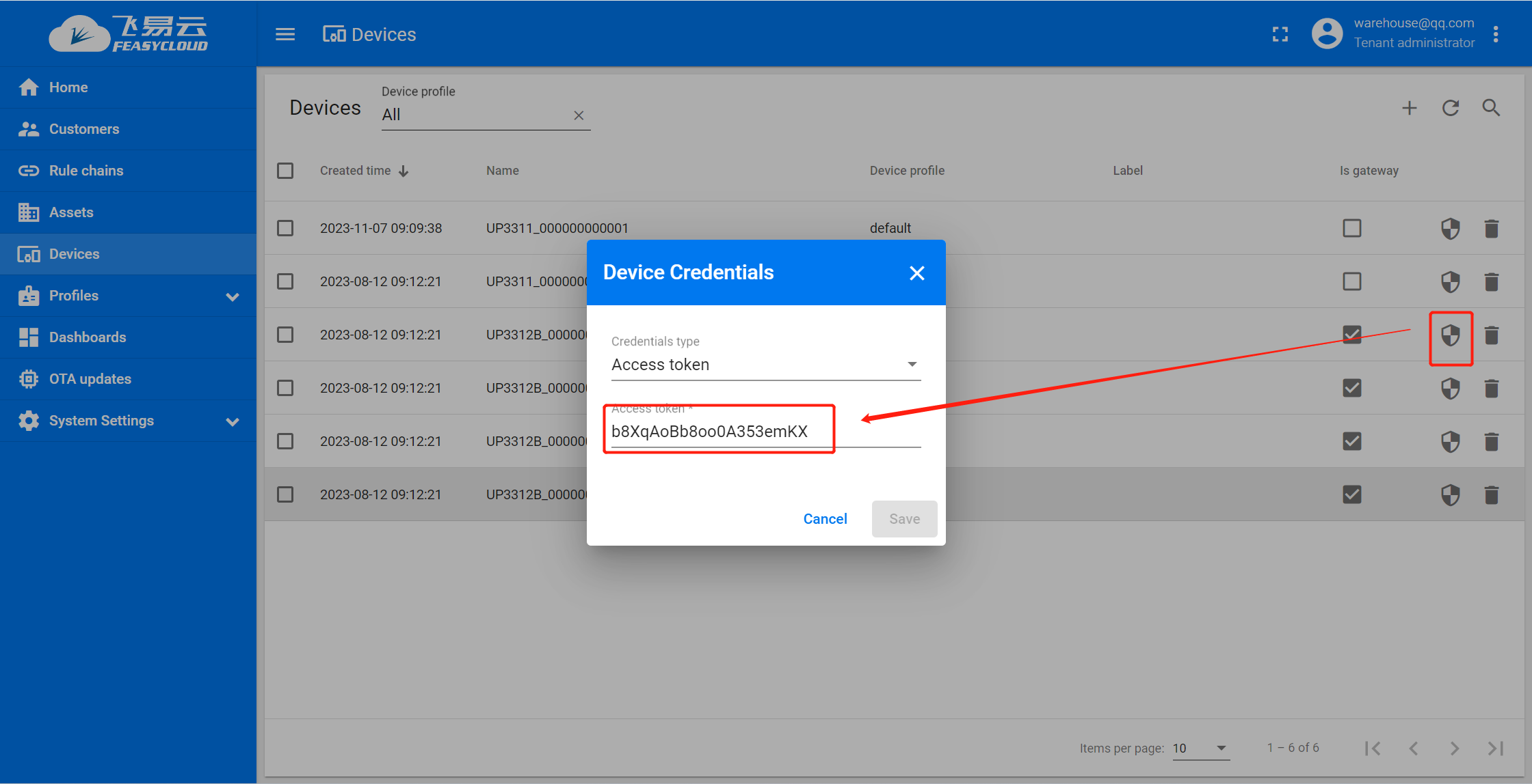
Step 3. Modify the credentials of the gateway, and the credentials are obtained from the gateway through the serial port AT command ( AT+TOKEN )
Gateway Distribution Network
The following is based on Windows 10 and Google Chrom browser 119 operating environment to demonstrate the operation instructions:
FeasyCloud provides network distribution functions.
FSC-UP3311 UWB gateway needs to be connected to the Internet, please use the SSID information and corresponding password of the WiFi AP that can be connected to the Internet to connect the gateway device to the network.
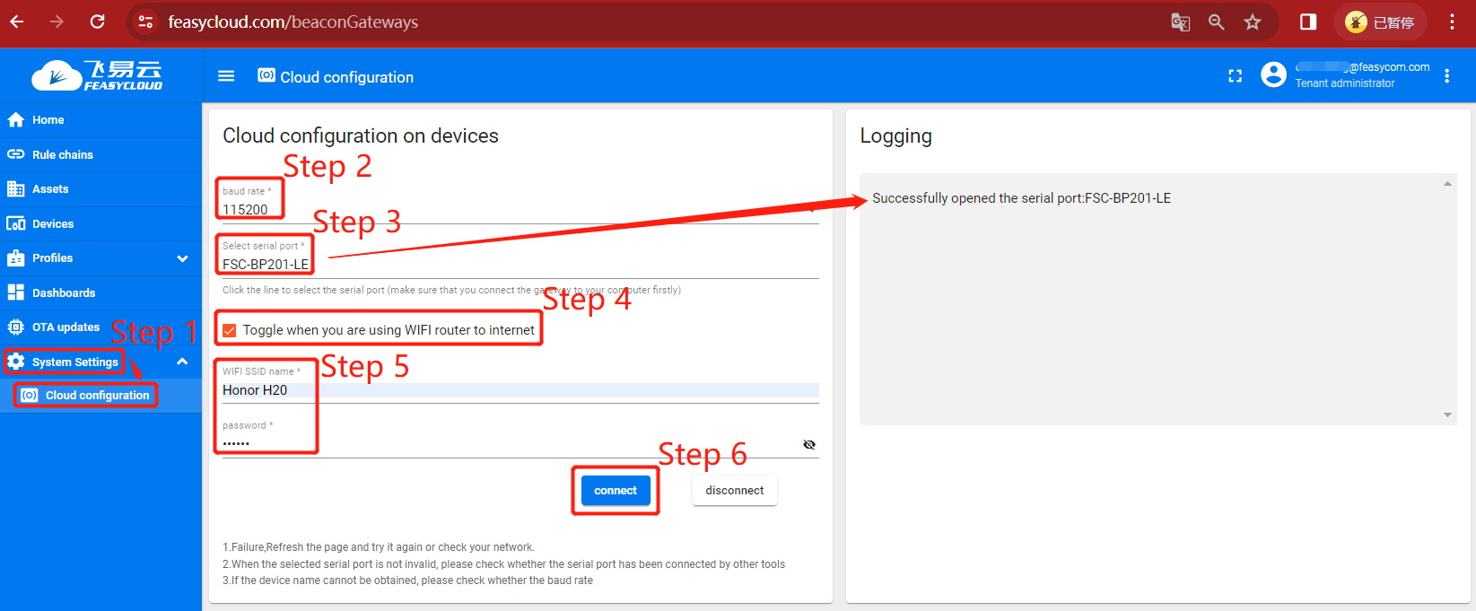
Step 1. In FeasyCloud-Home ,navigate to the configuration page under system setting - Cloud configuration in the left navigation menu;
Step 2. In the cloud configuration page, click baud rate and select the baud rate corresponding to the device. The general gateway program defaults to 115200;
Step 3.1 Connect your FSC-UP3312 UWB gateway ** to your computer via **Micro-USB cable. At the same time, a serial device will be added to your computer system, assuming that the serial port is COM2;
Step 3.2 In the cloud configuration page , click Select serial port. In the list of devices that pop up, select the corresponding serial port COM2 (Tip :you can plug and unplug the USB port to see the vanishing change of the serial port is the device serial port number).
After adding and connecting Successfully, in the Logging window on the right side of the cloud platform, ** successfully opened the serial port:xxxx** will be prompted, indicating that the device was successfully connected;
Step 4 Select Toggle when you are using WIFI router to internet : √ ;
Step 5. Enter the contents of the valid WiFi SSID name and ** Password ** fields of the WiFi AP you can connect to the Internet with;
Note
Only 2.4G band hotspots can be connected
Step 6. click connect ,your gateway device FSC-UP3312 will enter the automatic network, and the cloud device will be automatically added.
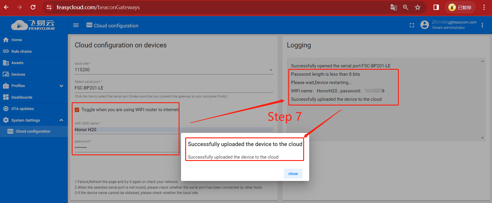
Step 7. In the Logging window, show the progress of the network connection and the progress of the cloud added gateway device.
If the addition is successful, the page will appear Successfully uploaded the device to the cloud in a popup ;
If there is an exception, please press the page popup to prompt the error message, or according to the Logging information on the right side of the page to troubleshoate.
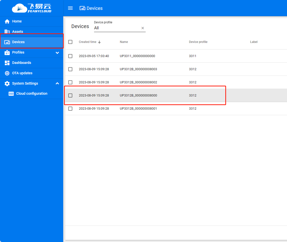
Check the gateway device status
Click on Devices and select the device name as shown below for UP3312B_000000008000 device
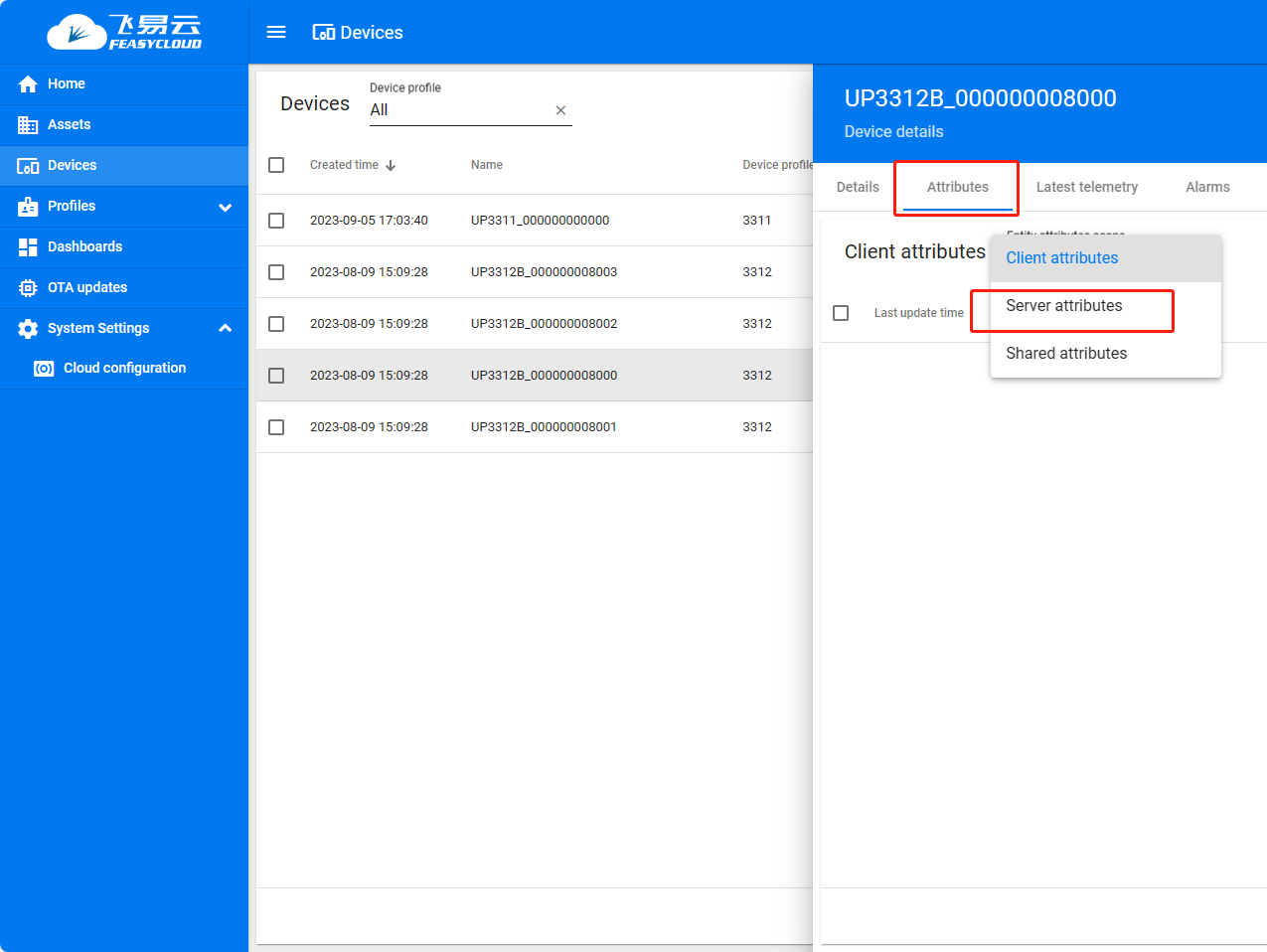
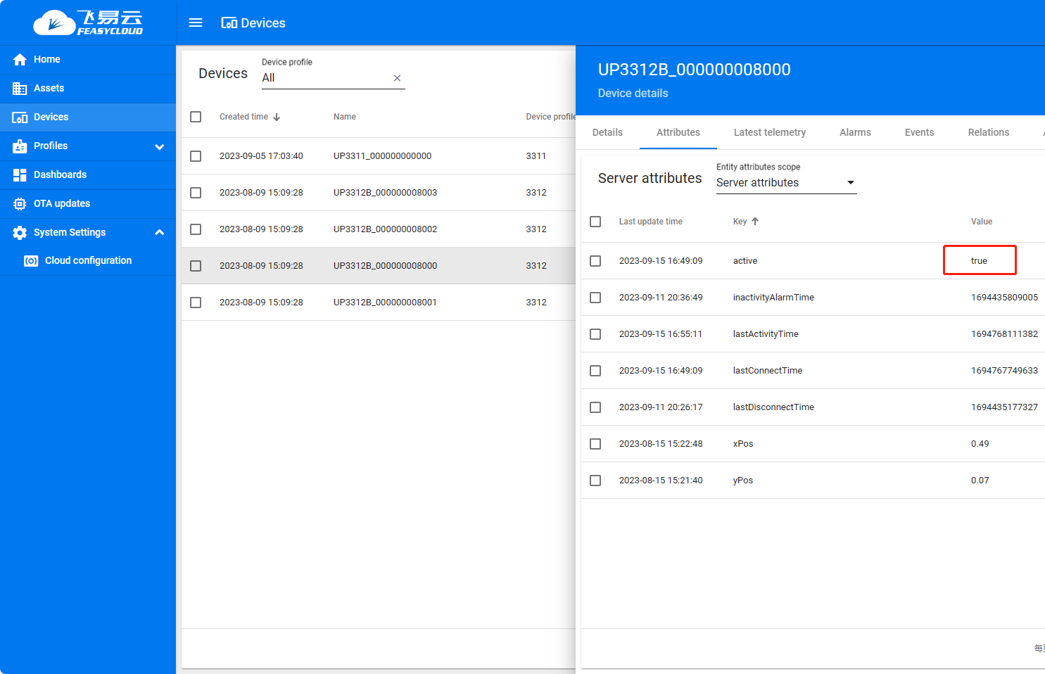
Click Attributes and select Server attributes
If the active status of the gateway is true, the distribution network is successful
View telemetry data
The gateway will automatically add the scanned 3311 Tags to the device list after adding the cloud
Click on the 3311 Tag for details and Latest telemetry to see the distance data between the Tag and the 4 base stations
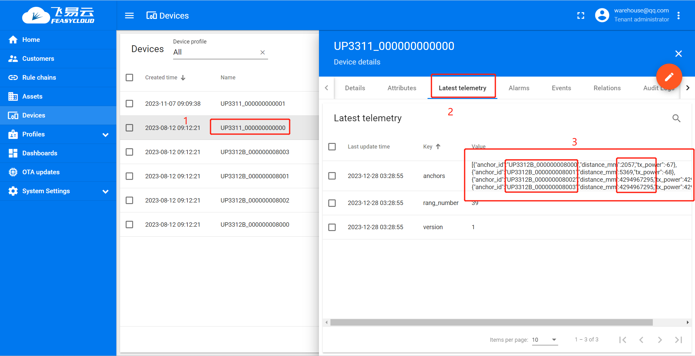
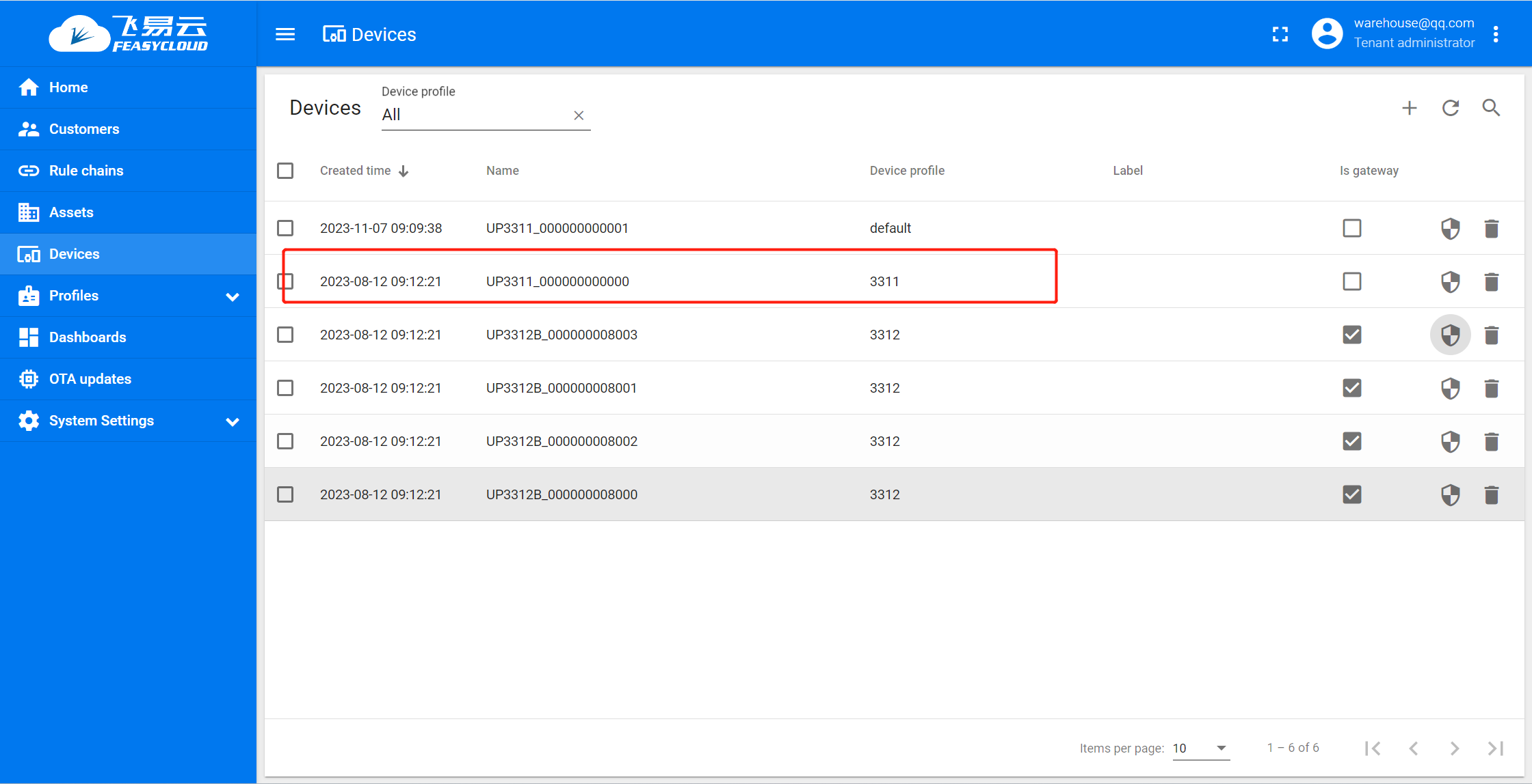
Add the remaining three base station devices, the Device Name needs to match the anchor_id in the telemetry
Interpretation of UWB Tag data
The teletransmission data of different devices are inconsistent. The devices in our set are mainly for UWB tags, and UWB tags will upload one-dimensional distance information from at least three Anchor points around it through teletransmission data.
Example :
a. Under the “ Latest telemetry “ page of the device UP3311_DC0D5000F0008, there is an item called “anchors”.Key value is a JSON array object ,form is : [ {anchor1},{anchor2},{anchor3}…] ; b. Specifically, each Anchor contains the following key content :
"anchor_id" : "UP3312_00123456789A""distance_mm" : 444We can use the Tag to set the “dis-tance_mm” information of the base station Anchor for ranging and obtain the relative position.
If we need to obtain the two-dimensional position information of the Tag in a plane, we need the distance information of the Tag from at least 3 base stations in the plane . FeasyCloud provides corresponding algorithms and visual monitoring 。
Visualize the location of the UWB Tag
Through the Dashboard of FeasyCloud, we can observe the actual position of the Tag in the plane, that is, the distance of the horizontal X and vertical Y relative to the coordinate origin, as shown in the following figure:
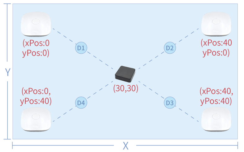
Origin of coordinates : Our top-left G1 position;
Relative location of other gateways : We need to specify G2, G3, G4 relative to the origin of the coordinates. That is, by setting the corresponding xPos, yPos in the device list in their Dashboard;
Relative position of the Tag : The relative position of the Tag is automatically calculated and displayed in the Dashboard.
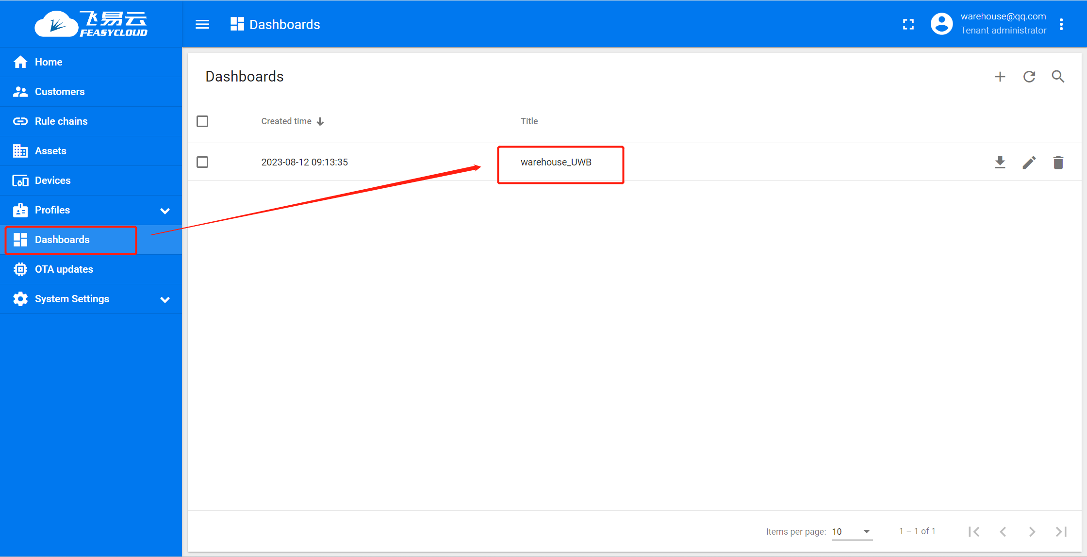
Visualize the positioning configuration process
Step 1. Enter the dashboard from the left Dashboard on the cloud platform, Click warehouse_UWB button.
- Step 2. Click on any Building , Click the Enter Edit Mode button in the bottom right corne,
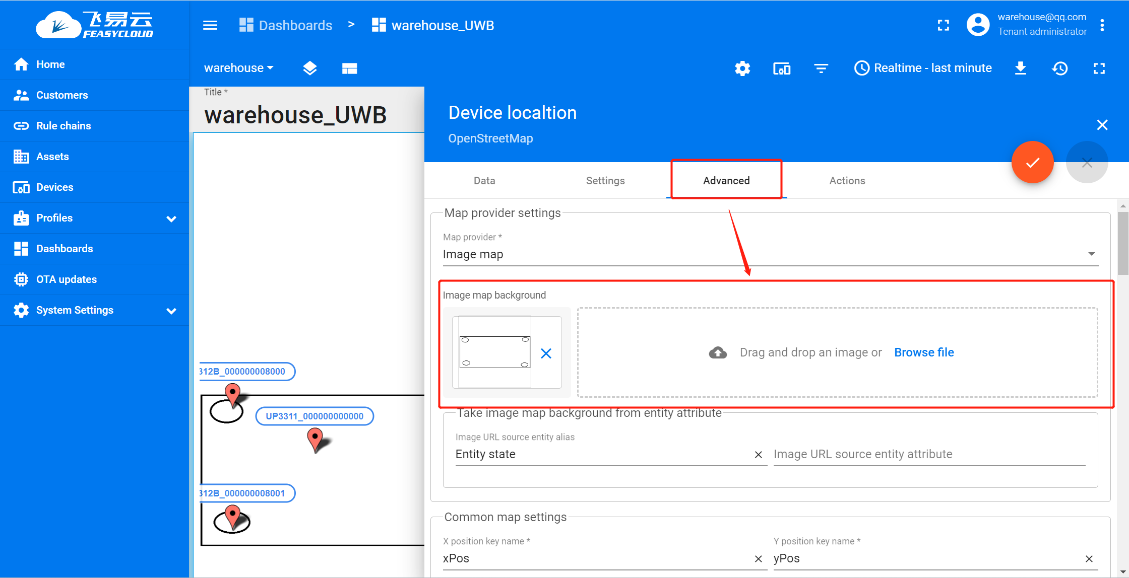
Click the Edit Widgets button in the top right corner of the right floor plan
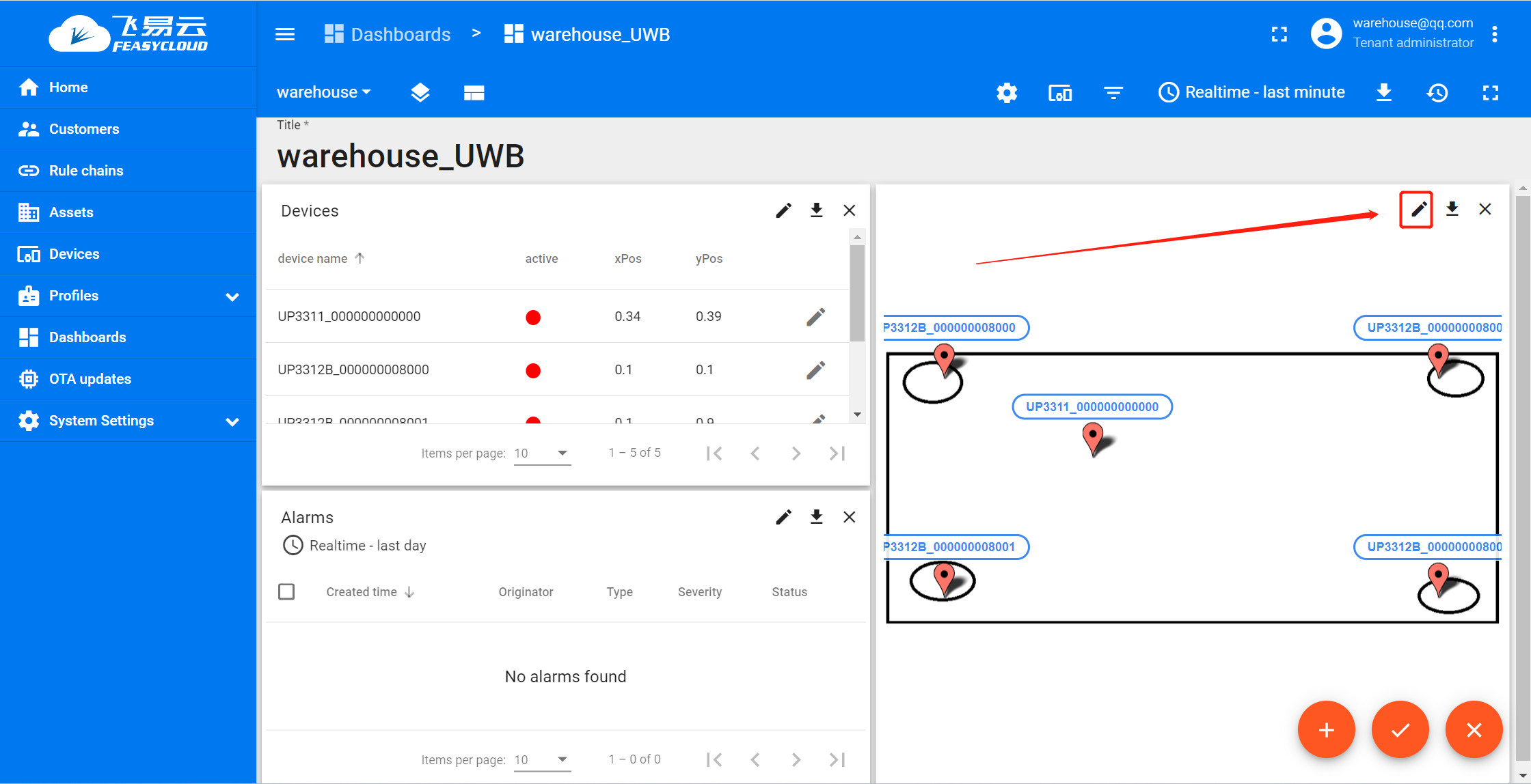
Step 3. Click Advanced - Browse file . Replace the background image of the warehouse, generally using a 2D plan of the room
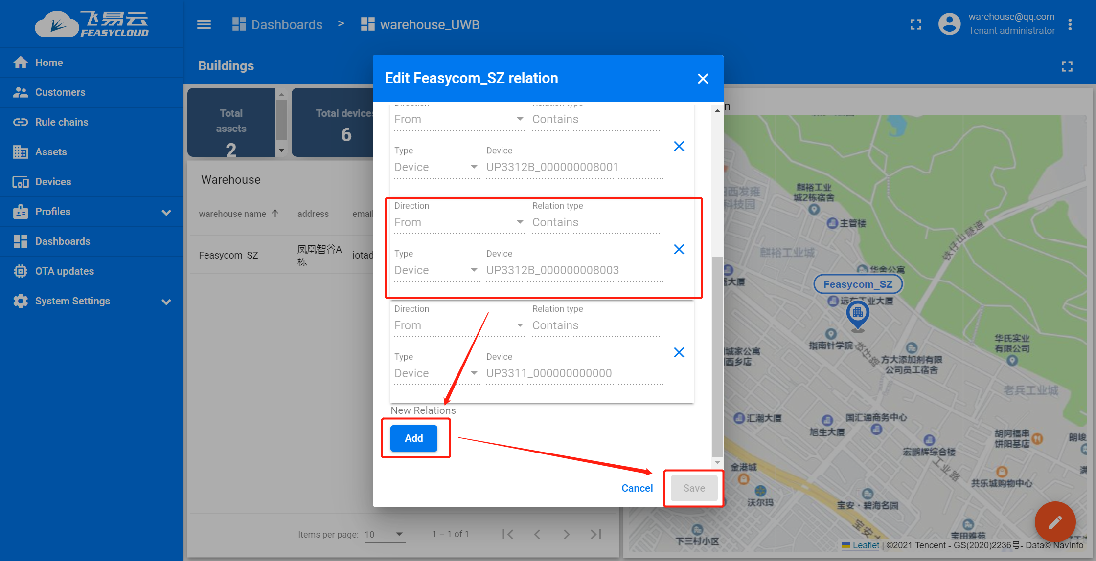
Step 4. In the Dashboards - warehouse_UWB . Click on the repository Relation, add both the base station and the tag to the repository,

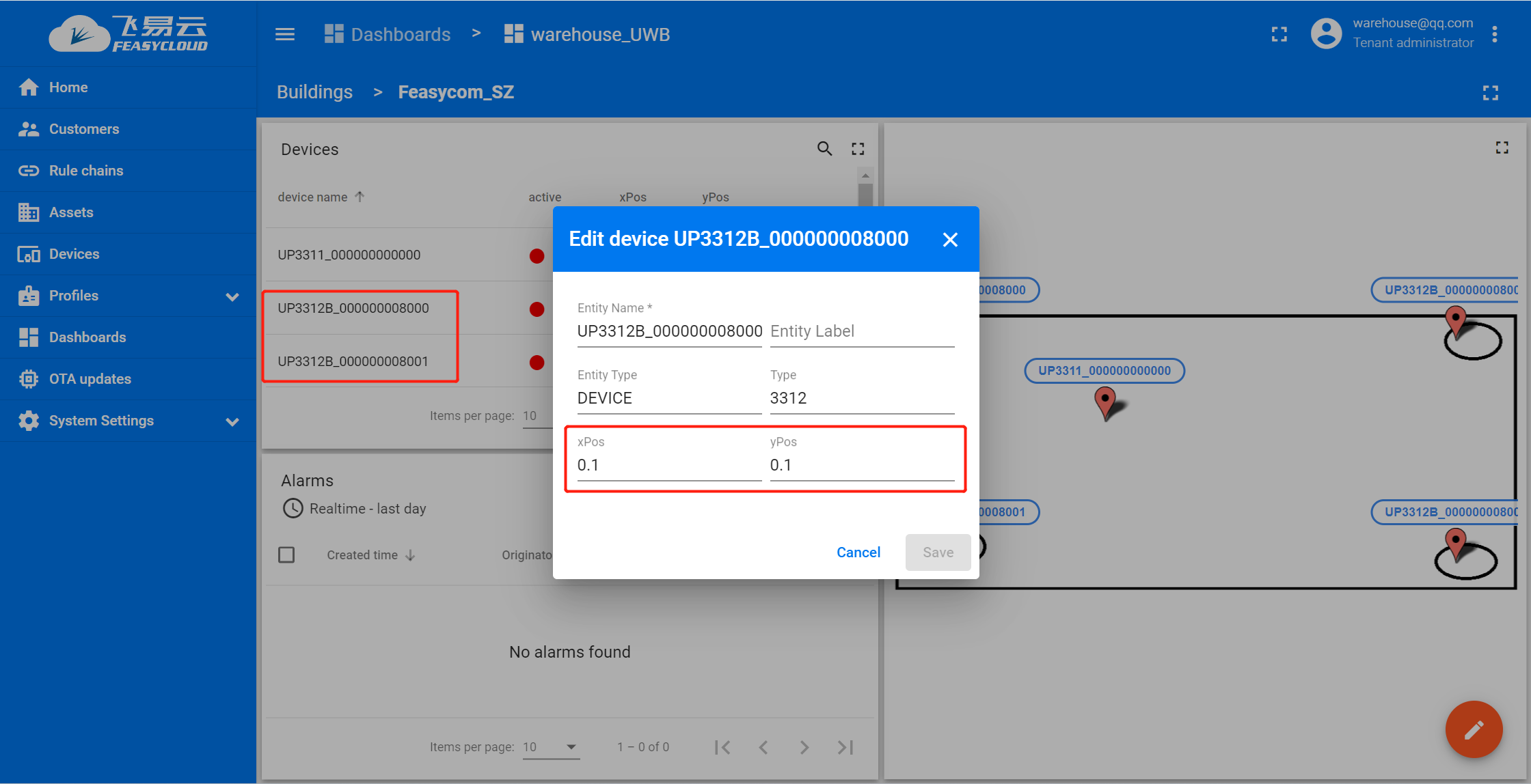
Step 5. Go to the repository where the device has been added. Under Devices, you can see all the devices that have been added. Click Modify after Base Station , set a relative coordinate for the base station . xPos and yPos can only be numbers between 0 and 1 . The coordinate of the base station gateway is (0,0) . The coordinates of other base stations are scaled based on distance from the base station gateway and the size of the room.
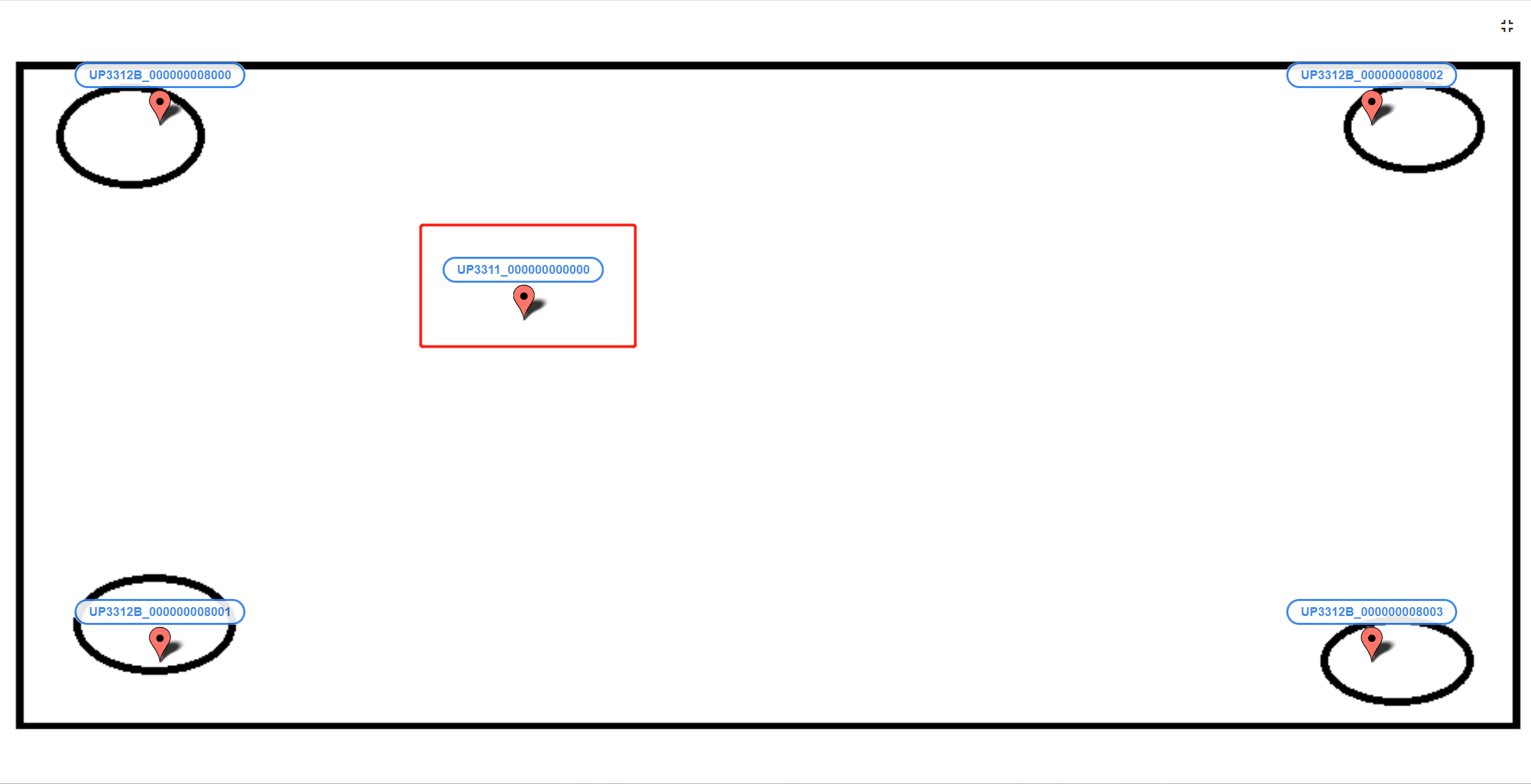
Step 6. After the configuration is completed, you can see the floor plan of the warehouse and the location of the 4 base stations on the right side of the warehouse, and the TAB will dynamically refresh the ICONS based on the real-time location.
More Advanced features
Note
Notice :You can explore through the demo dashboard, but be aware that this demo dashboard may be modified and updated at any time.
Contact Information
Shenzhen Feasycom Co.,Ltd.
Address : Rm 508, Building, Fenghuang Zhigu, NO.50, Tiezai Road, Xixiang, Baoan Dist, Shenzhen, 518100, China.
Telphone : 86-755-23062695
Sales Service : sales@feasycom.com
Support : support@feasycom.com
Home Page : www.feasycom.com
Support Forum : forum.feasycom.com