Development Examples
Network Configuration
FeasyBlue BLE Network Configuration
APP Download
User Guide
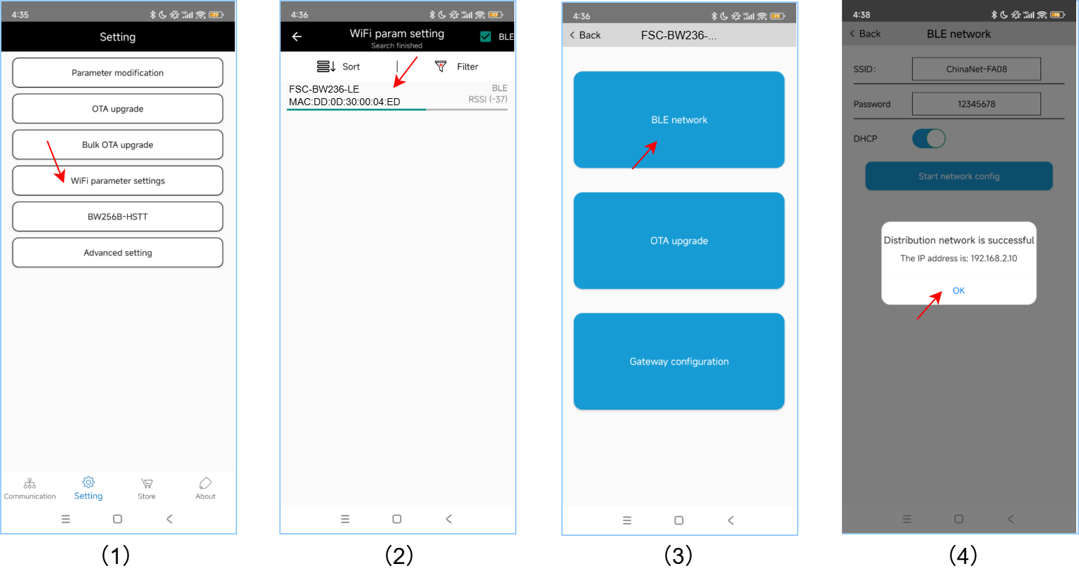
1.Open the FeasyBlue App and click on Setting - WiFi Parameter Settings to enter the WiFi param setting page.
2.On the WiFi param setting page, Check BLE , scan and select the WiFi param setting page.
3.Select and click on BLE Network to enter the BLE network page.
4.On the BLE network page, enter the enter the SSID 和 password of the Wi-Fi AP to be connected, and click Start network config.
5.After the distribution network is completed, It will show the Distribution network is successful and the IP address .
Example
Web Configuration
Enable Web Configuration function
Before performing web configuration, it is necessary to first enable the web configuration function on the module. For FSC-BW236, this function can be enabled via the AT command AT+WEBCFG=1 .
Send:     >>AT+ROLE=2                                       //Set module to AP mode
Response: << OK

Send:     >>AT+WEBCFG=1                             //Enable Web Page provisioning
Response: <<OK
User Guide
Take operations on a mobile terminal (such as a mobile phone) as an example:
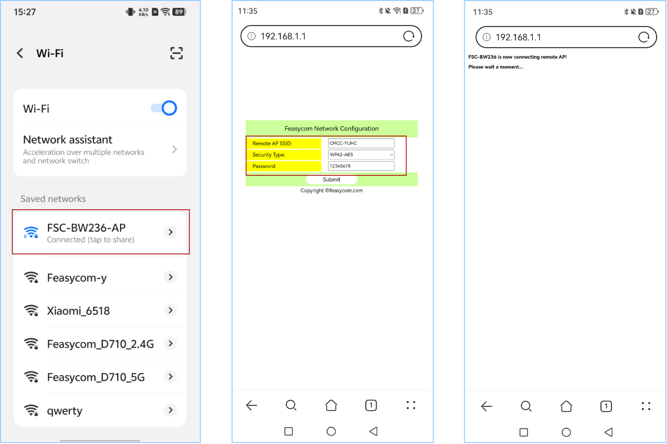
1.FSC-BW236 module acts as an AP. Mobile phones can connect to the module’s AP via Wi-Fi. For the FSC-BW236 general firmware, default the AP name is “FSC-BW236-AP” and the password is 12345678.
2.After connected, open your phone’s browser and enter the FSC-BW236 Local AP IP Address 192.168.1.1.
3.On the opened Feasycom Network Configuration page, enter the SSID and Password of the remote router device. And Click the Submit button to start network config.
4.After the network configuration is completed, the module will automatically connect to the remote router and response the WiFi status +WLANSTAT=3 .
5.Similarly, the same web configuration operation can be performed on a PC by simply repeating Steps 1 to 5 above.
Report: <<+WLANSTAT=3 // Module successfully connected to WiFi
Web Configuration Example
WPS Network Configuration
1.Enable the remote AP’s WPS function: Press the WPS button on the remote AP, and the AP will enter WPS network configuration mode. (Operation methods may vary depending on the brand or model of the AP device. For details, please refer to the official supporting manual of the AP device.)
2.Enable WPS network configuration: The FSC-BW236 module can use the command AT+WPSCFG=1 to enable WPS.
Send:     >>AT+WPSCFG=1               // Enable WPS network configuration
Response: <<OK
3.Wait for connection: After both the AP device and the Bluetooth device enter WPS mode, they will automatically scan and attempt to pair and connect.
4.After the network configuration is completed, the module will automatically connect to the remote router and response the WiFi status +WLANSTAT=3 .
Report: <<+WLANSTAT=3 // Module successfully connected to WiFi
Throughput Mode Application
What Is Throughput Mode?
FSC-BW236 Bluetooth & Wi-Fi module features two data transmission modes: Throughput Mode and Command Mode .
The default command mode of the general data transmission application firmware. If you need to switch, you can refer to [FSC-BW236 General Data AT Command Set] , and using the AT+TPMODE command.
The working mechanisms and differences of the two data transmission modes are as follows:
Throughput Mode :
Without Bluetooth or Wi-Fi connection , the data received through the serial port is parsed in the format of AT instructions;
Bluetooth or Wi-Fi connection has been established , all the data received through the serial port is sent to the remote end as is.
Command Mode :
Without Bluetooth or Wi-Fi connection , the data received through the serial port is parsed in the format of AT instructions;
Bluetooth or Wi-Fi connection has been established , The data received through the serial port is still parsed in the AT instruction format, which means data that needs to be sent to the remote end should be carried by AT commands.
Switch To Throughput Mode
Enter the Throughput Mode: Before establishing Bluetooth or Wi-Fi connection, the FSC-BW236 module can use the command AT+TPMODE=1 to activate the transparent transmission mode.
Send:     >>AT+TPMODE=1                     //Set it to throughput mode
Response: <<OK
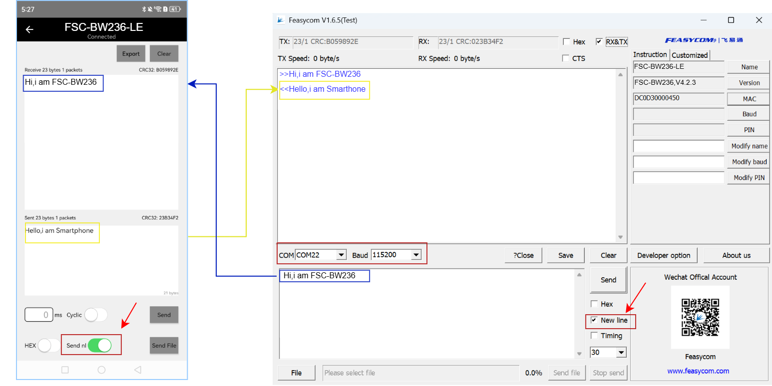
When Bluetooth or Wi-Fi connection has been established, exit throughput mode:
Send:     >> +++      //Send "+++". When operating on the host computer's serial port tool, please uncheck "New Line" at this time.
Response: << a                //Received response "a"
Send:     >> a                //Send "a". When operating on the host computer's serial port tool, please uncheck "New Line" at this time.
Response: << +ok      //Successfully exited
Note
Throughput Mode only takes effect when connections (such as Bluetooth, TCP/UDP) have been established. Therefore, the methods to exit transparent transmission also only work under such circumstances. When no connections have been established, you can directly use the AT command (AT+TPMODE) to switch modes.
The data format for sending and receiving mentioned above differs from that of AT commands. Standard AT commands end with <CR><LF> , while the above-mentioned control commands are strings that do not come with <CR><LF>.
Throughput Mode Application
Module to Phone Communication
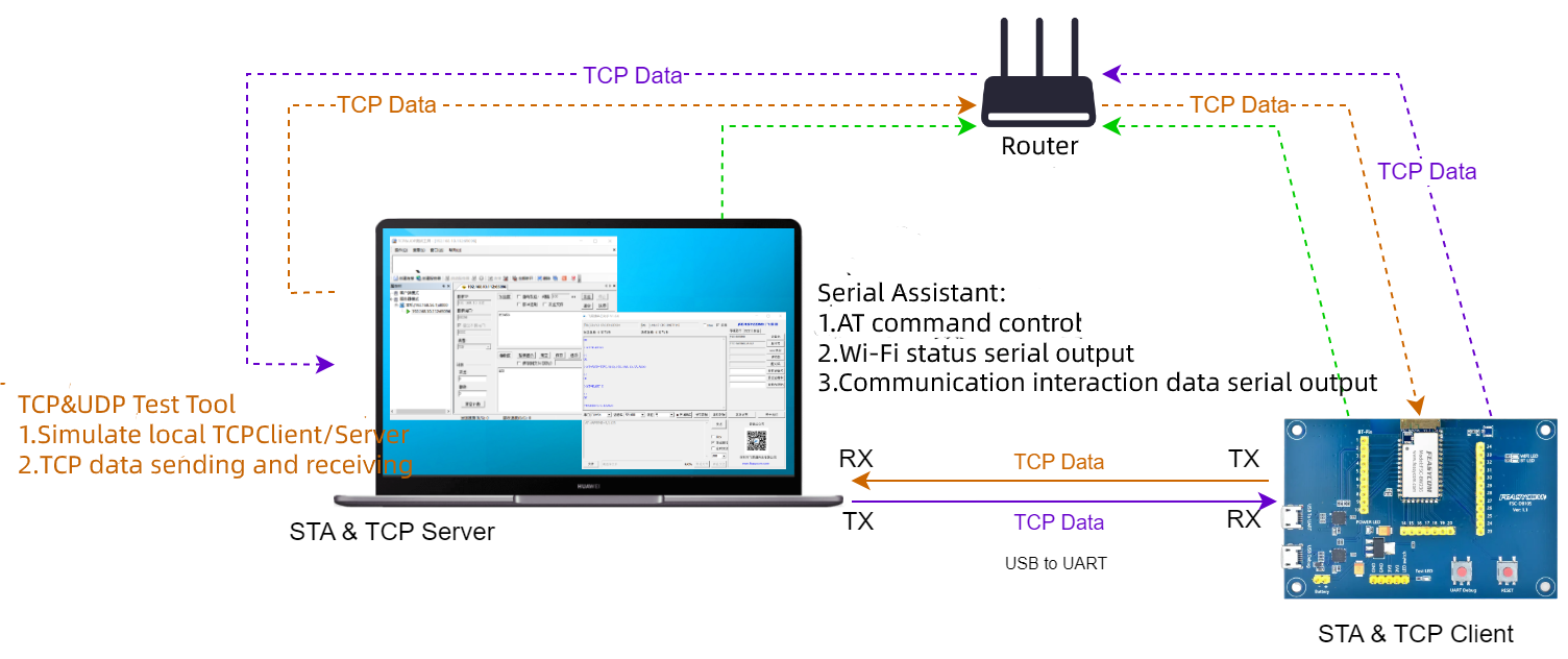
TCP Server Application
Tools
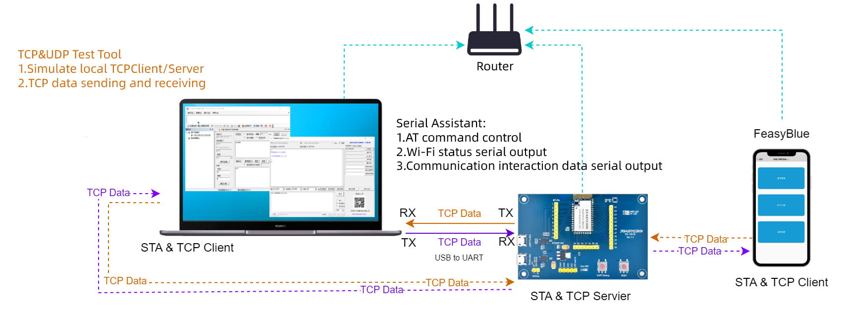
Feasycom Serial Port Tool : A serial communication analysis tool based on Windows PC.
(Option) TCP&UDP Test Tool : Optional third-party PC-based network test tool are available.
TCP Server Application Example
TCP Server Application Flowchart
TCP Server Application Description
1.Set the module to Wi-Fi mode. If it is already in the current mode, you can skip this step.
Send:     <<AT+ROLE=1
Response: >>OK
2.The module is connected to the AP hotspot.
Send:     <<AT+RAP=SSID,PASSWORD
Response: >>OK
3.Query the IP address of the module to confirm that it has been connected to the network.
Send:     <<AT+LIP
Response: >>+LIP=192.168.0.97  //For local examples, please refer to the actual IP address obtained by connecting to the AP
Response: >>OK
4.Set the module to TCP server with port 9100.
Send:     <<AT+SOCK=TCPS,9100
Response: >>OK
5.To create a TCP server for the module.
Send:     <<AT+WLANC=3
Response: >>OK
6.The PC and the module (FSC-BW236) are connected to the same AP hotspot. On the PC, a third-party network debugging tool is used to create an IP address for the TCP connection to the TCP Server (module) as a TCP client. And after establishing a TCP connection, send TCP data to the TCP Server (module), such as 1234567890.
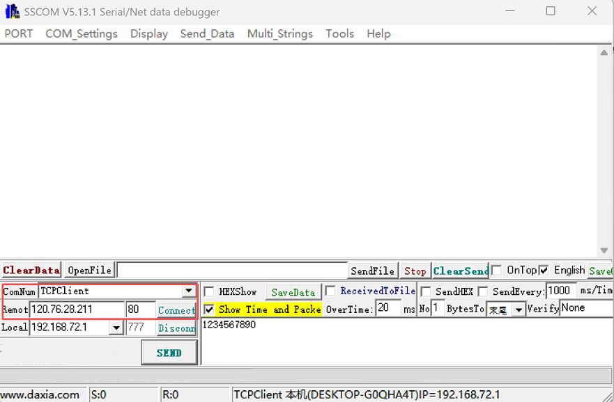
7.The module receives TCP data sent by the TCP Client. In instruction mode, an example of the received data format serial port response is as follows:
Response: >>+WFDATA=0,10,1234567890   //Supports simultaneously receiving data sent from multiple TCP clients to the TCP Server, with the first parameter being the connection ID
Response: >>+WFDATA=1,10,1234567890
Response: >>+WFDATA=2,10,1234567890
8.The module supports the simultaneous reception of data sent from multiple TCP clients to the TCP Server. The first parameter is the connection ID. In command mode, an example of the AT command operation is as follows:
Send:     <<AT+WFSEND=0,3,abc
Response: >>OK
TCP Client Application
Tools
Feasycom Serial Port Tool : A serial communication analysis tool based on Windows PC.
(Option) TCP&UDP Test Tool : Optional third-party PC-based network test tools are available.
TCP Client application Example
TCP Client Application Flowchart
TCP Client Application Description
1.Set the module to Wi-Fi mode. If it is already in the current mode, you can skip this step.
Send:     <<AT+ROLE=1
Response: >>OK
2.Connect the module to the AP hotspot.
Send:     <<AT+RAP=SSID,PASSWORD
Response: >>OK
3.To query the IP address of the module.
Send:     <<AT+LIP
Response: >>+LIP=192.168.0.97   //For local examples, please refer to the actual IP address obtained by connecting to the AP
Response: >>OK
- 4.Connect the PC and the module to the same AP hotspot. Use a third-party network debugging tool on the PC to create a TCP Server.
For example, the IP address of the TCP Server is 192.168.0.79 and the port number is 8080.
5.Set the module as TCP client and configure the IP and port number of the remote TCP Server.
Send:     <<AT+SOCK=TCPC,9100,192.168.0.79,8080
Response: >>OK
6.The module acts as a TCP client to initiate the establishment of a TCP connection with the remote TCP Server.
Send:     <<AT+WLANC=3
Response: >>OK
7.After the TCP connection is successfully established, the PC-end network debugging tool will display the successful connection, as well as the data sending area and receiving area. TCP data sending and receiving can be carried out, such as sending data 1234567890 to the remote TCP Client module
8.The module receives TCP data sent from the TCP Server. In instruction mode, an example of the received data format response is as follows:
Response: >>+WFDATA=3,10,1234567890
UDP Application
UDP Application Flowchart
UDP Application Description
1.Set the Wi-Fi mode. If you are already in the current mode, you can skip this step
Send:     <<AT+ROLE=1
Response: >>OK
2.Connect to AP
Send:     <<AT+RAP=SSID,PASSWORD
Response: >>OK
3.Query the IP address of the module
Send:     <<AT+LIP
Response: >>+LIP=192.168.0.97   //For local examples, please refer to the actual IP address obtained by connecting to the AP
Response: >>OK
4.Set module as UDP
Send:     <<AT+SOCK=UDP,4000
Response: >>OK
5.Start UDP Server
Send:     <<AT+WLANC=3
Response: >>OK
6.The PC and the module are connected to the same hotspot. On the PC, a network test tool is used to start UDP Client with the target IP 192.168.0.97 and the target port number 4000.
7.Receive data
Response: >>+WFDATA=4,10,1234567890
8.Send data
Send:     <<AT+WFSEND=4,3,abc
Response: >>OK
Note
To use throughput mode, simply send AT+TPMODE=1 before setting the Wi-Fi mode.
SSL Client Application
SSL Client Application Flowchart
SSL Client Application Description
1.Set the Wi-Fi mode. If you are already in the current mode, you can skip this step
Send:     <<AT+ROLE=1
Response: >> OK
2.Connect to AP
Send:     <<AT+RAP=ssid,password
Response: >> OK
3.Query the IP address of the module
Send:     <<AT+LIP
Response: >>+LIP=192.168.0.97   //For local examples, please refer to the actual IP address obtained by connecting to the AP
Response: >>OK
4.Set the module as SSL client and configure the remote server and port number
Send:     <<AT+SOCK=SSL,9100,httpbin.org,443
Response: >>OK
5.The module initiates a connection to the remote end as an SSL client
Send:     <<AT+WLANC=3
Response: >> OK
6.Send relevant requests, such as GET requests
Send:     <<AT+SSLSEND=40,GET /get HTTP/1.1\\r\\nHost: httpbin.org\\r\\n\\r\\n
Response: >> OK
7.Receive data
Response: >>+SSLDATA=Specific data
Note
To use throughput mode, simply send AT+TPMODE=1 before setting the Wi-Fi mode.
MQTT Application
MQTT Application Flowchart
MQTT Application Description
1.Set the Wi-Fi mode
Send:     <<AT+ROLE=1
Response: >>OK
2.Connect to AP
Send:     <<AT+RAP=SSID,PASSWORD
Response: >> OK
3.Query the IP address of the module
Send:     <<AT+LIP
Response: >>+LIP=192.168.0.97   //For local examples, please refer to the actual IP address obtained by connecting to the AP
Response: >>OK
4.Set the BROKER address
Send:     <<AT+BROKER=gpssensor.ddns.net
Response: >>OK
5.Set User Name
Send:     <<AT+USERNAME=admin
Response: >>OK
6.Set Password
Send:     <<AT+MQTTPWD=12345678
Response: >>OK
7.Subscribe to topics
Send:     <<AT+SUBTPC=user/get,0
Response: >> OK
8.Connect to MQTT
Send:     <<AT+WLANC=4
Response: >> OK
9.Receive the data sent by the cloud platform
1234567890
10.Send data to the cloud platform
Send:     <<AT+MQTTPUB=user/post,0,3,abc
Response: >>OK