Data Communication Principles
1. Communication Principle
The FSC-BT836x series Bluetooth dual-mode data modules enable wireless communication between devices based on the SPP (Serial Port Profile) and BLE (Bluetooth Low Energy) dual-mode protocols.
SPP Mode: Emulates traditional serial port communication, establishing a virtual serial link through the RF layer. It supports continuous large data transfers (e.g., file transfer) and is suitable for scenarios like printers.
BLE Mode: Utilizes an event-driven, low-power architecture, defining a “Service-Characteristic” model via the GATT protocol for intermittent small data interactions (e.g., sensor data), ideal for IoT devices.
Both modes share the underlying RF hardware and switch automatically via the protocol stack. The module communicates with the host device (phone/MCU) through the UART interface using AT commands or transparent data transmission to establish connections, exchange data, and manage status.
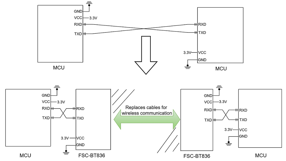
As shown in the figure, the Bluetooth module replaces the physical cable in full-duplex communication. A device like an MCU (left) sends data via its TXD pin to the Bluetooth module (left). The module’s RXD port receives the UART data and automatically transmits it via radio waves over the air to the remote Bluetooth module. The remote Bluetooth module (right) receives the airborne data and delivers it via its TXD pin to the local device, like an MCU (right).
2. MCU-to-Module Communication
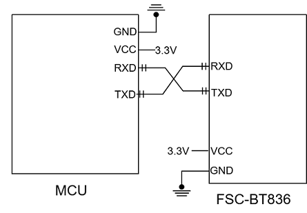
This diagram illustrates the connection between a master MCU (Microcontroller Unit) and an FSC-BT836 Bluetooth module via cross-connected serial ports, enabling command interaction between the master and the Bluetooth module to support wireless communication functions. It is applicable to IoT devices, remote control, and other scenarios.
Serial Communication Interface: The master MCU’s transmit pin (MCU_TX) is cross-connected to the Bluetooth module’s receive pin (UART_RX), and the master MCU’s receive pin (MCU_RX) is similarly connected to the Bluetooth module’s transmit pin (UART_TX), forming a bidirectional data transmission channel.
Power and Grounding: The Bluetooth module is powered by 3.3V through the VDD_3V3 pin and shares a common ground (GND) with the master MCU, ensuring level compatibility and signal stability.
3. Module-to-Module Communication
Two FSC-BT836 Bluetooth modules can establish a Bluetooth connection automatically upon power-up.
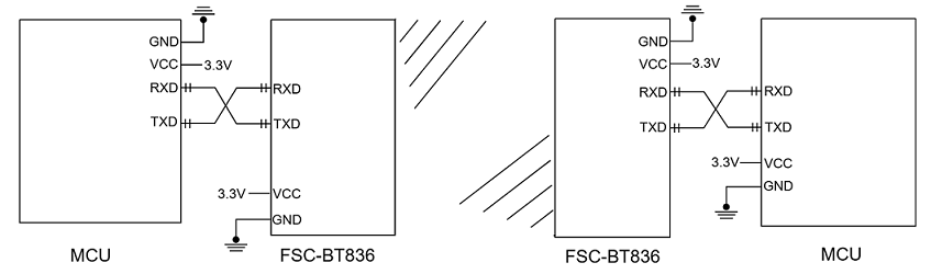
A module can act as a master device to connect to a slave device. The host can send commands to control the module for Bluetooth scanning, connection establishment, data transmission, and connection termination.
4. Module-to-Phone Communication
4.1 Why do we need to use an app on a mobile phone for Bluetooth connection and communication?
Native phone Bluetooth functionality primarily supports common use cases like audio transfer and file sharing. Some Bluetooth peripheral devices can be connected via the phone's built-in settings (e.g., Bluetooth speakers, headphones, keyboards, mice). However, when a peripheral device, like a module only supporting SPP/GATT protocols, cannot be connected via native phone settings, a specific mobile application, such as the FeasyBlue app, is generally required for connection.
4.2 Communication Application Diagram

Bluetooth Module Side (FSC-BT836): Continuously transmits broadcast data after power-up.
Mobile Terminal : Can discover the broadcast packets via scanning and initiate a connection request to the module (FSC-BT836). Upon successful connection, the Bluetooth module (FSC-BT836) will pull the connection status pin HIGH and respond to status indication commands (valid in Command Mode) to notify the host of the successful Bluetooth connection.
Host: Can send data to the remote (Mobile Terminal) Bluetooth via the UART through the Bluetooth module. Conversely, the remote (Mobile Terminal) Bluetooth can also send data back to the host.