Development Examples
Data Throughput Mode Application
What is Throughput Mode?
FSC-BT836x series dual-mode Bluetooth data transmission modules have two data transmission modes: Throughput Mode and Command Mode.
The generic data throughput firmware for the FSC-BT836x series modules default to throughput mode. To switch modes, refer to the FSC-BT836x General Dual-Mode Data AT Command Set and use the AT+TPMODE command.
The operation and differences between the two modes are as follows:
Throughput Mode:
Bluetooth Not Connected: Data received via UART is parsed as AT commands.
Bluetooth Connected: All data received via UART is sent as-is to the remote Bluetooth device. It does not contain any data headers or framing and does not require AT commands to send data.
Command Mode:
Bluetooth Not Connected: Data received via UART is parsed as AT commands.
Bluetooth Connected: Data received via UART is still parsed as AT commands. It will contain specific response indication headers and framing. Data must be sent to the remote device using AT commands, such as AT+SPPSEND or AT+LESEND .
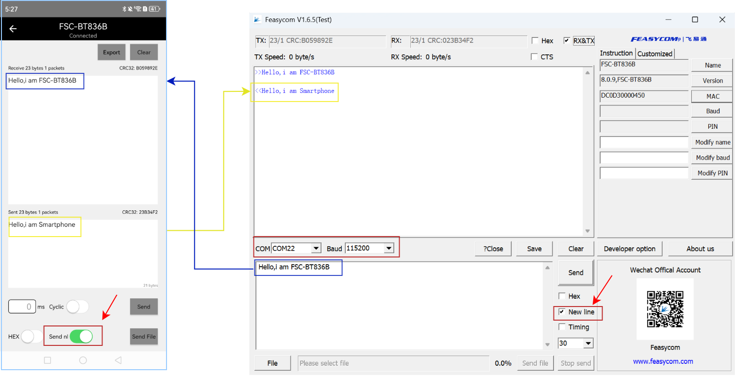
Module to Phone Application
Module: After power-on, the module will continuously send broadcast packet data.
Phone: Open the FeasyBlue APP , scan for nearby Bluetooth device advertisements, find the target Bluetooth module, and establish a connection.
Connection Success: After successful connection, the status pin of the module will pull up the level, indicating that the connection has been established.
Data Transmission: After successful connection, in the througput mode, the module will automatically transmit the serial port data it receives to the remote end (mobile phone side) via air.
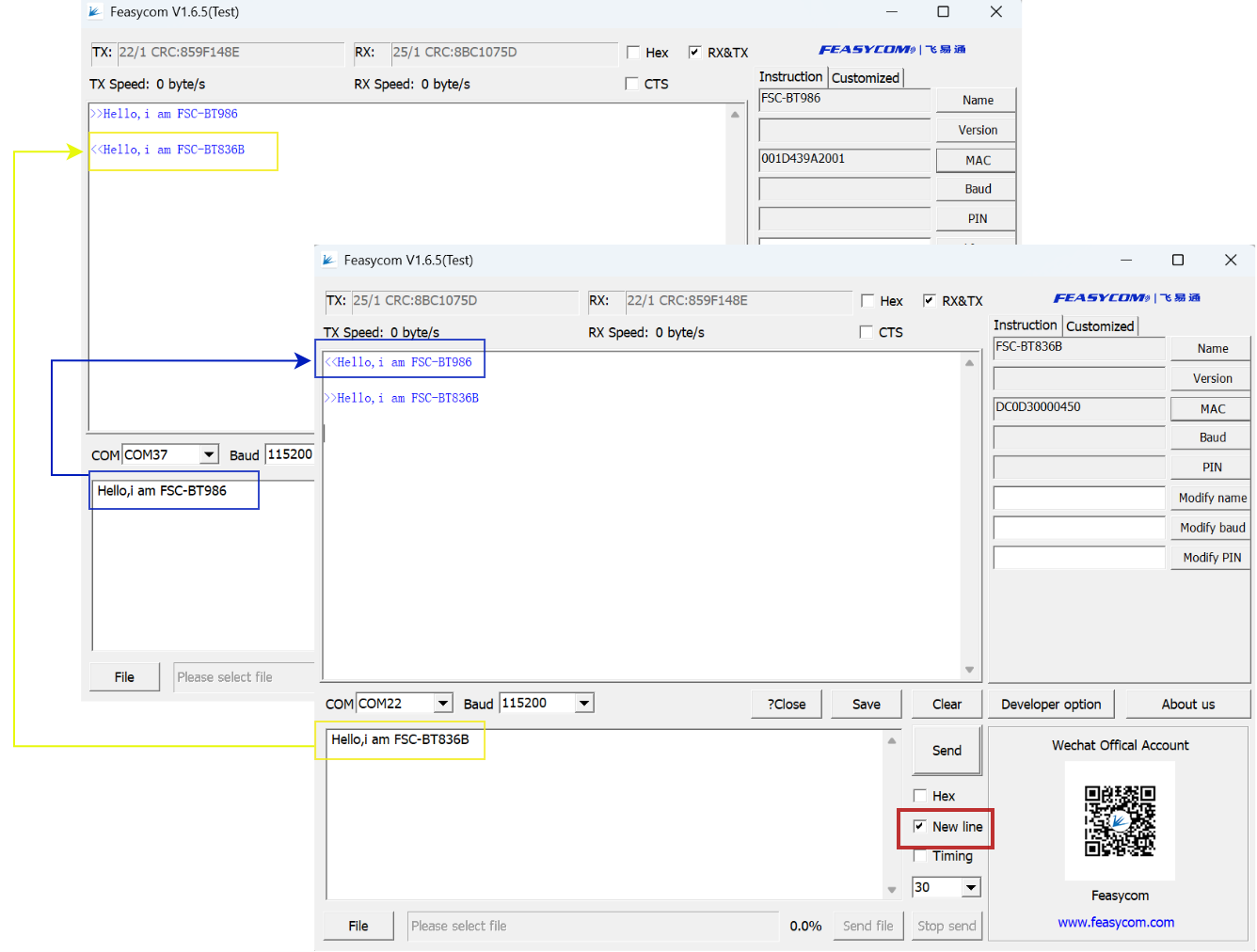
Module to Module Application
Demonstration of SPP communication and data throughput transmission between an FSC-BT836x and an FSC-BT986 Bluetooth module, as follows:
1.Scan for nearby SPP devices
FSC-BT836B scans for nearby Bluetooth SPP devices, as follows:
 1Send: <<AT+SCAN=1                // Scan for nearby Bluetooth SPP devices
 2Response: >>OK
 3Response: >>+SCAN={                   // Scan started
 4Response: >>+SCAN=1,2,DC0D3000135F,-63,10,FSC-BT986
 5Response: >>+SCAN=2,2,DC0D3023CA1C,-71,14,0000-1007Z ggg
 6Response: >>+SCAN=3,2,DC0D30000235,-72,10,FSC-BT826F
 7Response: >>+SCAN=4,2,DC0D300017A8,-75,11,FSC-BT3721V
 8Response: >>+SCAN=5,2,A4405B28A838,-89,10,AirGo AS01
 9Response: >>+SCAN=6,2,C02E25D07080,-58,7,OPPO K3
10Response: >>+SCAN=7,2,1063C8585846,-68,15,DESKTOP-BVPUURD
11Response: >>+SCAN=8,2,5820590F1E83,-71,7,Redmi 7
12Response: >>+SCAN=}                  // Scan ended
2.Establish SPP connection request
FSC-BT836x establishes an SPP connection with the FSC-BT986 using the AT+SPPCONN command, as follows:
1Send: <<AT+SPPCONN=DC0D3000135F      // Initiate an SPP connection request to the remote FSC-BT986
2Response: >>OK
3.SPP Connected
In throughput mode, after a successful Bluetooth connection, the UART will not receive event response indicators. The connection status can be determined by the level state of the status pin (e.g., Pin 10) on the FSC-BT836x, as follows:
High Level (H): Indicates Bluetooth is successfully connected.
Low Level (L): Indicates Bluetooth is not connected or the connection has been disconnected.
4.Send data
Throughput mode is enabled by default in the generic data transmission firmware. After SPP connected, data can be sent directly without using AT commands, as follow:
Read/Write Module Default Parameters
When Bluetooth is not connected, the module parses UART data as AT commands. The host can query and modify the module’s default parameters. As follow:
Write the device name to ABC
Read the device name
Read the Bluetooth address
Data Transmission Flow
Upon power-up, the module continuously transmits advertisement data. A remote Bluetooth device (e.g., phone) can discover these advertisement packets via scanning and initiate a connection request to the module.
Upon successful connection, the module pulls its connection status pin HIGH to notify the host of the successful Bluetooth connection.
The host can send data to the remote Bluetooth device via the Bluetooth module, and the remote Bluetooth device can also send data to the host.
Module Acts as Master to Connect to Remote Device
The module can act as a master device to connect to a slave device. The host can send commands to control the module to perform scanning, connection, and disconnection.