Hardware Design
Module Pin Diagram
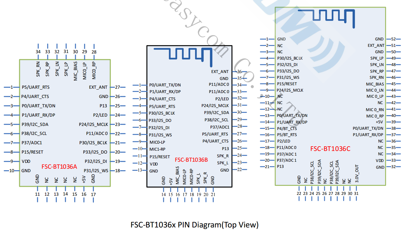
Pin Description
BT1036A |
BT1036B |
BT1036C |
Pin Name |
Type |
Pin Descriptions |
|---|---|---|---|---|---|
21 |
5 |
4 |
I2S_CLK |
I/O |
I2S BCLK |
19 |
7 |
5 |
I2S_IN |
I |
I2S DATA IN |
20 |
6 |
6 |
I2S_OUT |
O |
I2S DATA OUT |
18 |
8 |
7 |
I2S_WS |
I/O |
I2S SYNC |
8 |
11 |
8 |
RESET |
I |
Low level reset |
3 |
1 |
13 |
UART_TX |
O |
UART_TX |
4 |
2 |
14 |
UART_RX |
I |
UART_RX |
2 |
3 |
15 |
UART_CTS |
I/O |
UART flow control pin (not required by default) |
1 |
4 |
16 |
UART_RTS |
I/O |
default as power amplifier control pin |
24 |
32 |
17 |
LED0 |
I/O |
In pairing mode, a square wave is output. When Bluetooth is connected, the output is a high level. |
22 |
33, 34 |
18 |
LED1 |
I/O |
SPP/GATT is not connected. The output is at low level. When connected, the output is at high level. |
10 |
13 |
32 |
GND |
GND |
GND |
9 |
12 |
33 |
VDD |
VDD |
3.3V power supply, it is recommended to use LDO |
28 |
18 |
40 |
MIC_RP |
Audio |
MIC0/Line_IN differential R input, positive |
/ |
/ |
41 |
MIC_RN |
Audio |
MIC0/Line_IN differential R input, negative |
29 |
9, 17 |
43 |
MIC_LP |
Audio |
MIC0/Line_IN differential L input, positive |
/ |
/ |
44 |
MIC_LN |
Audio |
MIC0/Line_IN differential L input, negative |
30 |
16 |
45 |
MIC_BIAS |
Audio |
MIC Power Supplies |
/ |
19, 23 |
/ |
SPK_L |
Audio |
Line out, left (16/32 0 load cannot be connected) |
/ |
20, 24 |
/ |
SPK_R |
Audio |
Line out, right(16/32 0 load cannot be connected) |
34 |
/ |
46 |
SPK_RN |
Audio |
Headphone/speaker differential R output, negative |
33 |
/ |
47 |
SPK_RP |
Audio |
Headphone/speaker differential R output, positive |
32 |
/ |
48 |
SPK_LN |
Audio |
Headphone/speaker differential L output, negative |
31 |
/ |
49 |
SPK_LP |
Audio |
Headphone/speaker differential L output, positive |
27 |
36 |
51 |
EXT_ANT |
ANT |
External antenna connect pin |
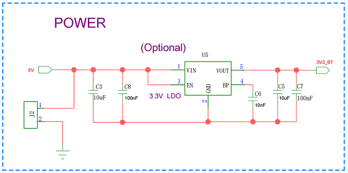
Power-on Circuit Design
The power supply needs to be stable at 3.3V.,If the power supply is unstable, the module will not be able to start properly, or there will be abnormalities in the function application.
If it is a 5V to 3.3V power supply, you can refer to the following optional schematic design suggestions:
Hardware Design Note
Simple testing environment, just connect VDD / GND / UART_RX / UART_TX.
After drawing the PCB circuit schematic, please send it to Feasycom for review to avoid suboptimal Bluetooth distance.