FSC-DB006 User Guide
[Version: 1.0] [中文版]
This guide introduces how to use the FSC-DB006 and provides further information about this development board.
Overview
FSC-DB006 is a rapid test board equipped with a USB interface. It is compatible with various Feasycom Bluetooth data transmission modules adopting the 10mm×11.9mm stamp hole 20-Pins package, such as the FSC-BT691, FSC-BT630, FSC-BT681, FSC-BT671x series, etc. Compared with using the Bluetooth module alone, its built-in USB enables direct connection to Windows PC, which not only saves time but also ensures stability during testing.
When used with Feasycom’s UART Communication Testing Tool, users can fully control the Bluetooth module via AT commands, facilitating an efficient development and testing process.
This development kit supports SPP, GATT, and HID protocols, further enhancing its flexibility in adapting to diverse applications.
|
|
|---|---|
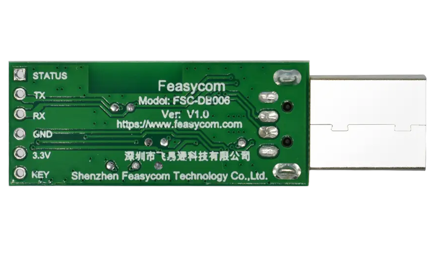
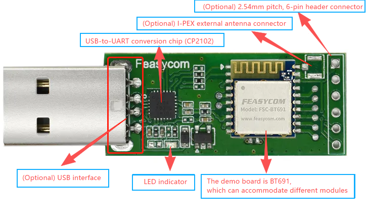
FSC-DB006 With FSC-BT691module - Side |
FSC-DB006 With FSC-BT691module - Back |

Scope of Application
Applies to :
FSC-BT691
FSC-BT630
FSC-BT681
FSC-BT671x Series
…
and other Feasycom Bluetooth modules with 10mm×11.9mm stamp-type 20-pin package, for data transmission communication development.
Functional Components
What You Need
Take FSC-DB006 with BT691 an example :
Required Hardware
1 x FSC-DB006-BT691 : an FSC-DB006 development board integrated with Feasycom FSC-BT691 (optional) Bluetooth dual-mode data transmission module.
1 x PC(Windows / Mac)
Software and Setup
Serial_Driver : CP210x Universal Driver for Windows PC, generally plug-and-play, install this driver if the PC fails to recognize the device in specific environments.
Feasycom Serial Port Tool : A serial communication analysis tool based on Windows PC.
FeasyBlue App : Feasycom APP & SDK resource supporting Android and iOS, which enables functions such as Bluetooth BLE & SPP data communication test, Feasycom module firmware version reading, firmware OTA upgrade, OTA command, parameter configuration, etc.
Communication Interface : UART
UART Configuration: 115200/8/N/1 (Feasycom general firmware default)
Hardware Access
Power-on Options
3V3 / GND pin power supply
USB 5V Power Supply
Warning :
The above power supply modes must not be connected simultaneously, as this may damage the development board and/or the power source.
Hardware Access Note
Before powering on, ensure the development board is intact and all components are secure without looseness or shorts.
Development board connects to a PC via a USB.
After powering on, the LED lights up steadily, indicating the module is powered normally and ready for test.
Communication Test
1.Power Supply Connection
Connect the intact development board FSC-DB006-BT691 to a PC via USB;
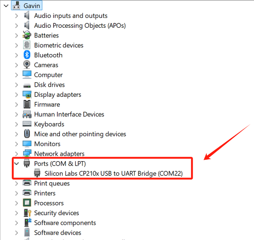
2.Serial Port Recognition
The PC detects the USB serial device and generates a virtual COMx.
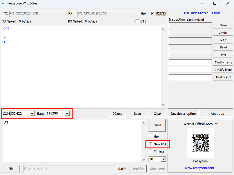
3.UART Communication Test
Run the Feasycom Serial Port Tool on the PC, set the correct COM and Baud, and check the New Line.
Send the UART communication test command AT. If the response is OK, it indicates the serial communication test is successful.
Command |
AT\r\n |
|---|---|
Response |
\r\nOK\r\n |
Description |
Test the UART communication between HOST and Module after power on, baudrate changed, etc. |
Contact Information
Shenzhen Feasycom Co.,Ltd.
Address : Rm 508, Building, Fenghuang Zhigu, NO.50, Tiezai Road, Xixiang, Baoan Dist, Shenzhen, 518100, China.
Telephone : 86-755-23062695
Support : support@feasycom.com
Sales Service : sales@feasycom.com
Home Page : www.feasycom.com
Support Forum : forum.feasycom.com