FSC-DB008 User Guide
[Version: 1.0] [中文版]
This guide will introduce how to use the FSC-DB008 audio and data transmission development board, and provide more information about this development board.
Overview
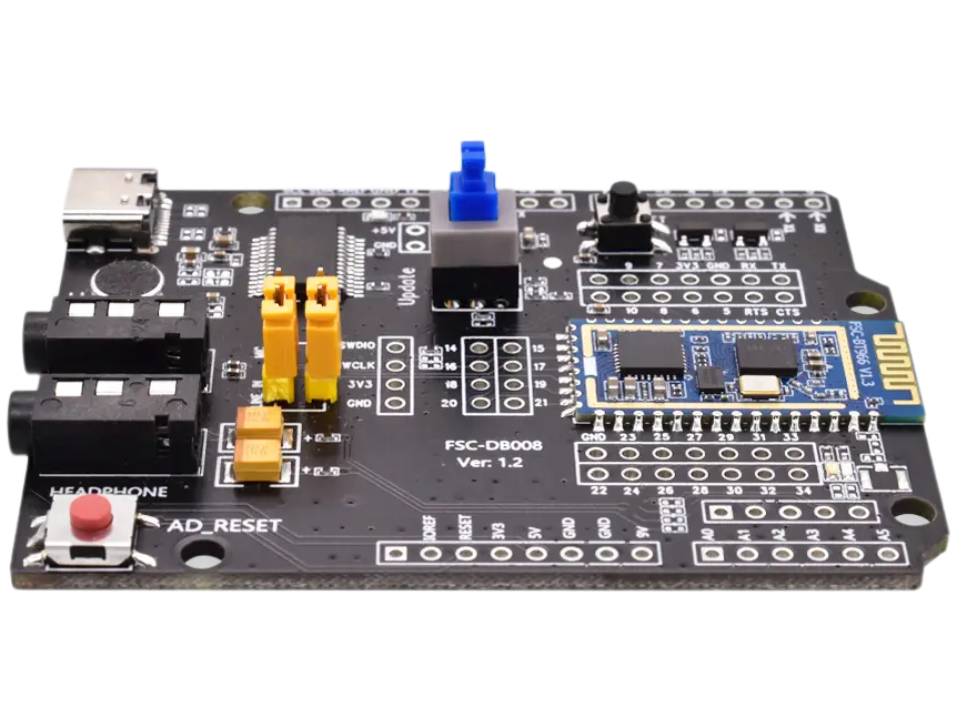
The FSC-DB008 Development Board integrates Type-C (supporting UART/USB/charging/power supply), audio input/output, a microphone, a lithium battery, buttons, a reset button, 2.54mm-pitch pin headers, and status indicator LEDs. It can be used with our company’s serial assistant and AT commands for function testing, helping customers familiarize themselves with our products, shorten the development cycle, and improve efficiency.
The FSC-DB008 is also a plug-and-play sub-development board designed specifically for Arduino UNO, enabling Arduino developers to evaluate Feasycom Bluetooth audio modules more effectively.
|
|
|---|---|
FSC-DB008 with FSC-BT966 module - Side |
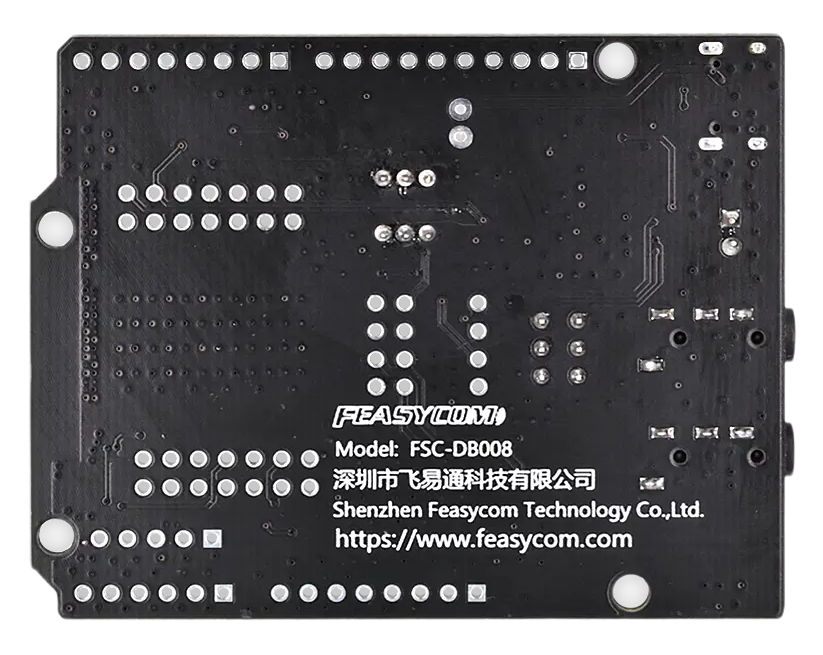
FSC-DB008 with FSC-BT966 module - Back |
Scope of Application
Applies to :
FSC-BT1036B
FSC-BT936B
FSC-BT966
FSC-BT909C
…
and other Feasycom Bluetooth audio modules for application development.
Functional Components
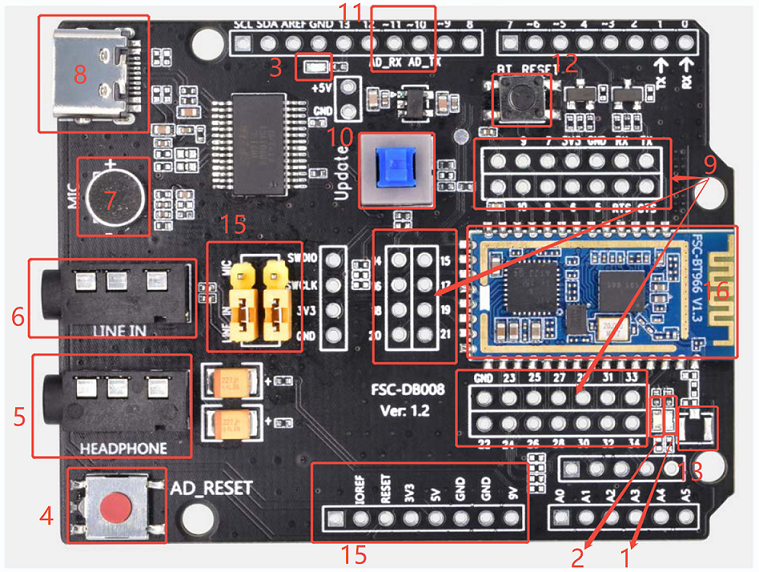
Description by labeled number
No. |
Component |
Description |
|---|---|---|
1 |
Indicator LED (LED1) |
Bluetooth status indicator LED (LED1); red LED stays on when the device is connected. |
2 |
Indicator LED (LED2) |
Bluetooth operation indicator LED (LED2); blue LED flashes when the device is disconnected, and stays on when connected. |
3 |
Indicator LED (LED3) |
Arduino reset LED; blue in color. |
4 |
Arduino Board Reset Key |
Arduino reset button. |
5 |
Headphone |
SPK_Out; standard 3.5mm headphone output interface. |
6 |
Line IN |
Line_In; standard 3.5mm audio input interface. |
7 |
MIC |
Microphone audio input interface. |
8 |
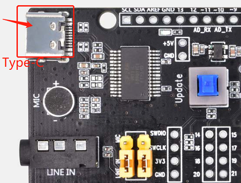
Type-C |
Type-C power supply/serial data communication interface. |
9 |
Module Pin Expansion |
Pin header interface for module pin expansion. |
10 |
Key Port |
Download key (for BT966 only). |
11 |
Arduino UART-TX/RX |
Pin header interface for Arduino UART-TX/RX expansion. |
12 |
BT Reset |
Bluetooth reset button. |
13 |
RF(external) |
IPEX patch position for external antenna. |
14 |
Arduino Power |
Power/multi-function expansion pin header for Arduino. |
15 |
MIC/Line_IN select |
Switch for MIC/Line_IN selection. |
16 |
Module Placement |
The sample shown in the diagram is the BT966 module. |
What You Need
Required Hardware
1 x FSC-DB008-BT1036B Development KIT : FSC-DB008 development board pre-integrated with a FSC-BT1036B (optional)
1 x USB-to-Type-C data cable
1 x PC(Windows / Mac)
1 x Mobile phone or music player
1 x AUX 3.5mm audio cable (optional)
1 x Bluetooth speaker or wired audio input Bluetooth headset (optional)
Software and Setup
Serial Driver : FT232r_Universal_Windows_Driver.zip for Windows PC, generally plug-and-play, install this driver if the PC fails to recognize the device in specific environments.
Feasycom Serial Port Tool : A serial communication analysis tool based on Windows PC.
FeasyBlue :Feasycom APP & SDK resource supporting Android and iOS platforms, which enables functions such as Bluetooth BLE & SPP data communication debugging, Feasycom module firmware version reading, firmware OTA upgrade,parameter configuration, etc.
Communication Interface:UART
UART Configuration:115200/8/N/1(Feasycom general firmware default)
Hardware Access
Power-on Options
The development board can be powered by any one of the following methods:
Type-C power supply (default)
3V3 / GND pin power supply
Note:Do not connect the above power supply modes simultaneously, as this may damage the development board and/or the power supply.
Hardware Access Note
Before power-on, confirm that the development board is intact and that no components are loose or stuck together.
Connect the development board to the PC using a USB-to-Type-C cable.
After power-on, the LEDs on the development board flash, indicating that the module is operational and ready for debugging.
Quick Start
Hardware Access and Start
Connect the Type-C port (Component 8) of the development board (FSC-DB008-BT1036B) to the PC using a USB-to-Type-C cable. A slow flash of Indicator LED (LED1) indicates that the module has started normally.
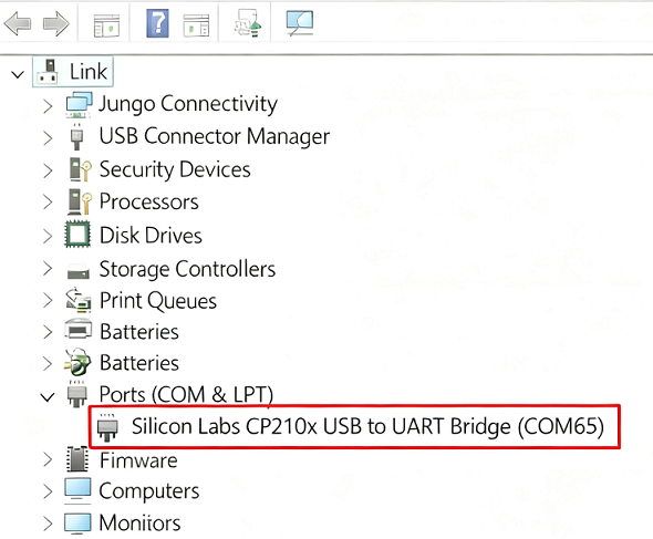
Serial Port Recognition
The device supports plug-and-play (no additional component control required). The PC will recognize the USB serial device and generate a virtual COMx port.
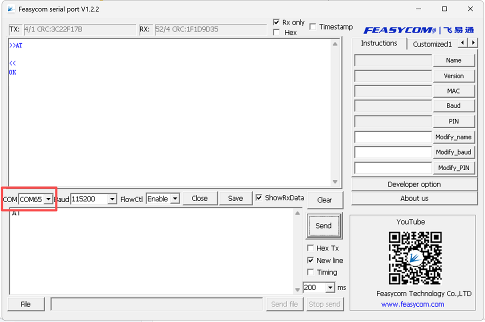
AT - Serial Communication Test
Open the Feasycom Serial Debug Assistant on the PC.Automatically detect or manually select the corresponding serial port (COMx),set the matching baud rate,(e.g., 115200), check Send New Line, and send the serial communication test command AT , If the response is OK , the serial communication test is successful. The command format and example are shown below:
Command |
AT\r\n |
|---|---|
Response |
\r\nOK\r\n |
Description |
Test the UART communication between HOST and Module after power on, baudrate changed, etc. |
Example:
send:     >>AT\r\n
response: <<\r\nOK\r\n   //Successfully connected.
Application Examples
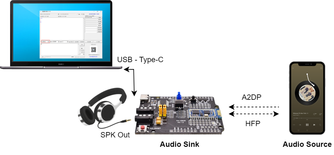
Audio Sink Mode
Application Diagram
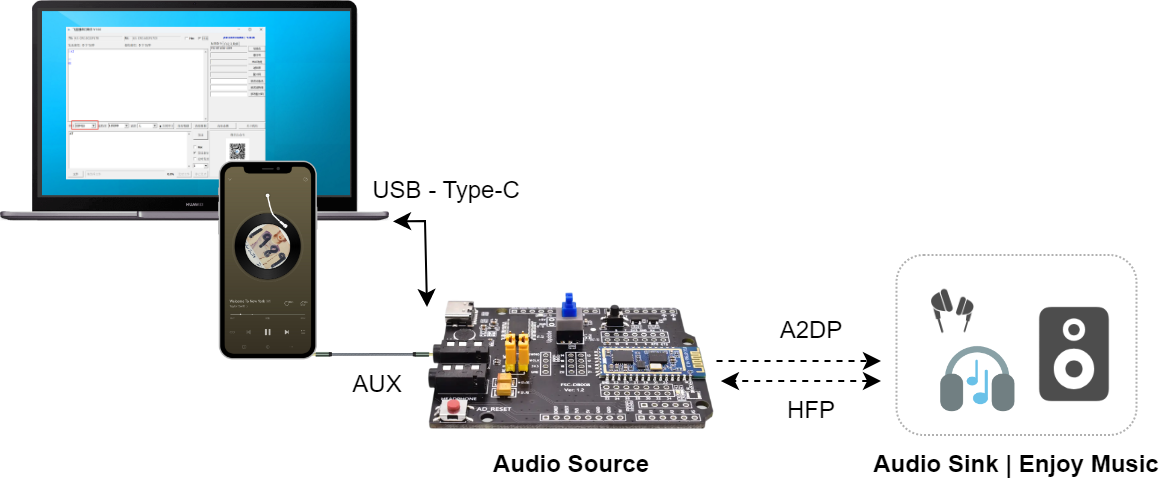
Audio Source Mode
Application Diagram
Contact Information
Shenzhen Feasycom Co.,Ltd.
Address : Rm 508, Building, Fenghuang Zhigu, NO.50, Tiezai Road, Xixiang, Baoan Dist, Shenzhen, 518100, China.
Telephone : 86-755-23062695
Support : support@feasycom.com
Sales Service : sales@feasycom.com
Home Page : www.feasycom.com
Support Forum : forum.feasycom.com