FSC-DB215 User Guide
[Version: 1.0] [中文版]
This guide will introduce how to use the FSC-DB215 and provide more information about this development board.
Overview
FSC-DB215 is a rapid evaluation board launched by Feasycom. It supports the Bluetooth 5.2 specification and is backward compatible with specifications such as Bluetooth 2.1 and 3.0, enabling simultaneous operation of audio streams (calls, music) and data transmission channels (Classic SPP, LE GATT).
It integrates a variety of functions, including a Type-C interface (supporting UART/USB/power supply), audio input and output, a microphone, function buttons, a reset button, 2.54mm pin headers, and LED status indicators.
In terms of protocol support, it is compatible with Profiles like HFP, A2DP, AVRCP, SPP, and GATT, and also supports LE Audio features such as BIS and CIS.
It is compatible with Feasycom’s Serial Assistant and AT commands for function testing, enabling developers to familiarize themselves with Feasycom’s products more quickly, shorten the development cycle, and improve efficiency.
|
|
|---|---|
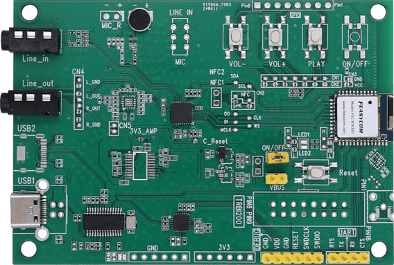
FSC-DB215 with FSC-BT631D module - Front |
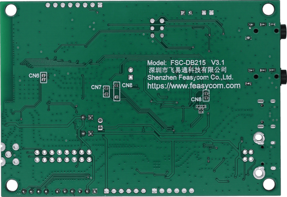
FSC-DB215 with FSC-BT631D module - Back |
Scope of Application
Applies to :
FSC-BT631D
FSC-BT631S
FSC-BT6038
FSC-BT1211
…
and other Feasycom Bluetooth audio modules for application development
Functional Components
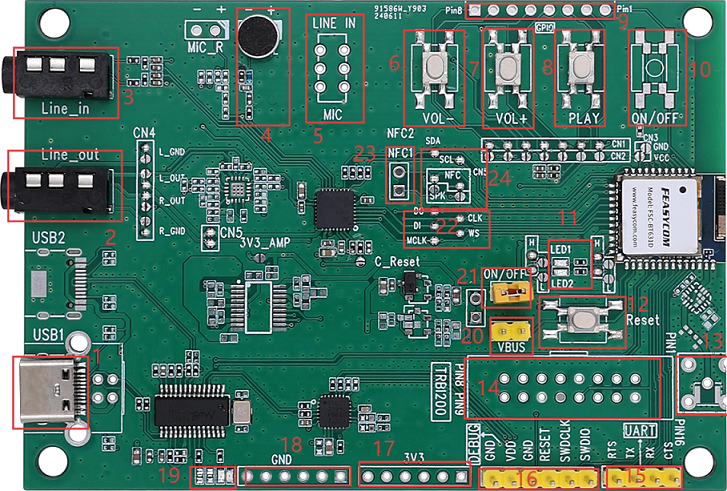
No. |
Components |
Description |
|---|---|---|
1 |
Type-C |
Power/Communicate with/Charge the battery via the module. |
2 |
Line_out |
Standard 3.5mm headphone output, capable of driving 16/32-ohm speakers, with a maximum of 60mW. |
3 |
Line_in |
Standard 3.5mm Audio interfaec. |
4 |
MIC_L/MIC_R |
HFP (used for incoming and outgoing calls, defaulting to the L channel) and applications requiring a microphone. |
5 |
Line in/MIC Switching |
Audio Input and Microphone Input Selection. |
6 |
VOL - |
Short press to decrease volume. |
7 |
VOL + |
Short press to increase volume. |
8 |
Play/Pause Button |
Music Play/Pause Button. |
9 |
Expansion Pin |
PIN1 - PIN8 Expansion Pins. |
10 |
ON/OFF |
Long press to power on/off. |
11 |
Module Status LED |
LED1: Green Light. |
12 |
Reset |
Short press to reset the module. |
13 |
SMA or IPEX External Antenna Expansion |
Switch to the external antenna. |
14 |
TRBI1200 |
The interface of the TRBI200 programmer, empty by default. |
15 |
UART Expansion |
Serial Port Expansion Pins. |
16 |
Debug and Download |
Expansion pins for reset, download, debug,etc. |
17 |
3V3 |
3V3 |
18 |
GND |
GND |
19 |
USB Communication LED |
Indicator lights for USB1-4 port working status. |
20 |
VBUS |
When the module inputs audio signals via USB, jumper connection is required. |
21 |
3V3 power supply |
3.3V power supply short - circuit enablement. |
22 |
I2S Test Point |
Reserved I2S test points for external communication testing. |
23 |
NFC |
NFC coil soldering pads (NFC functionality is available in some modules). |
24 |
NFC and SPK Switching |
NFC and SPK jumper selection. |
What You Need
Required Hardware
2 x FSC-DB215-BT631D(FSC-DB215 Development Board pre-integrated with FSC-BT631D,numbered DB1 and DB2 respectively)
2 x USB-to-Type-C male-to-male data cable
1 x PC(Windows / Mac)
1 x Mobile phone or Music player
1 x 3.5mm TRS Male-Male Auxiliary Cable (Optional)
1 x Bluetooth speaker or wired audio input Bluetooth headset (Optional)
Software and Setup
Serial Driver: CP210x_Universal Driver for Windows PC, generally plug-and-play, install this driver if the PC fails to recognize the device in specific environments.
Feasycom Serial Port Tool : A serial communication analysis tool based on Windows PC.
FeasyBlue :Feasycom APP & SDK resource supporting Android and iOS platforms, which enables functions such as Bluetooth BLE & SPP data communication debugging, Feasycom module firmware version reading, firmware OTA upgrade,parameter configuration, etc.
Communication Interface:UART
Serial Configuration:115200/8/N/1(Feasycom general firmware default)
Hardware Access
Power-on Options
The development board can use either of the following power supply methods:
Type-C power supply (default)
3V3 / GND pin power supply
Note:Do not connect the above power supply modes simultaneously, as this may damage the development board and/or the power supply.
Hardware Access Note
Before power-on, confirm that the development board is intact and that no components are loose or stuck together.
Connect the development board to the PC using a USB-to-Type-C cable.
After power-on, the LEDs on the development board flash, indicating that the module is operational and ready for debugging.
Quick Start
Hardware Access and Start
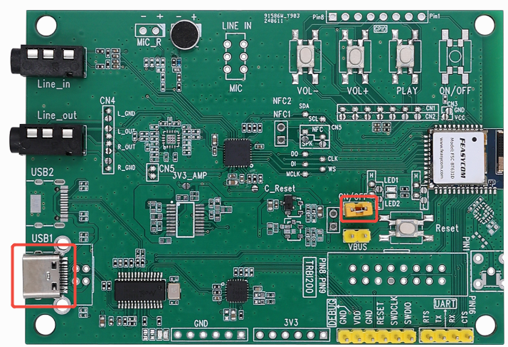
Connect the development board (FSC-DB215-BT631D) to your PC with a USB-to-Type-C cable via the Type-C port (component USB1). Set the power switch (component ON/OFF) to the shorted position, when LED1 blinks slowly, the module has started up correctly.
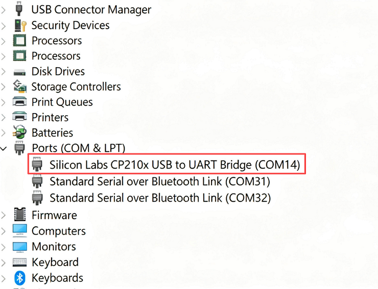
Serial Port Recognition
The device supports plug-and-play (no additional component control required). The PC will recognize the USB serial device and generate a virtual COMx port.
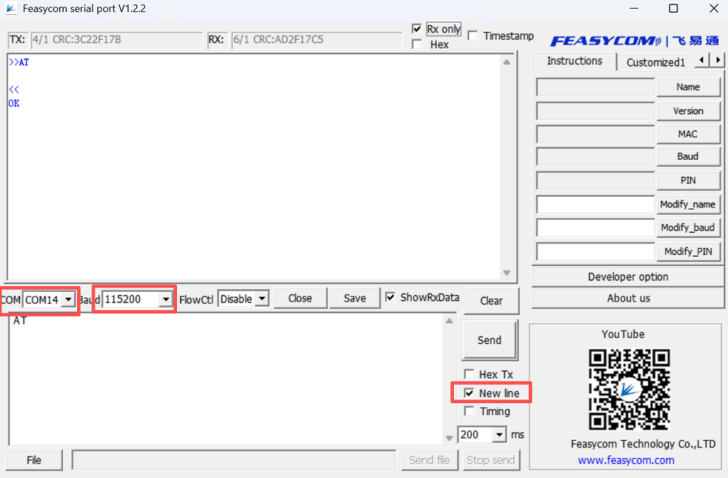
AT - Serial Communication Test
Command |
AT\r\n |
|---|---|
Response |
\r\nOK\r\n |
Description |
Tests UART communication between the host and the module, when power is on or the baud rate is changed. |
Example:
send:     <<\r\nAT\r\n
Response: >>\r\nOK\r\n
Application Examples
LE Audio BIS(Broadcast Isochronous Stream)Application
Application Diagram
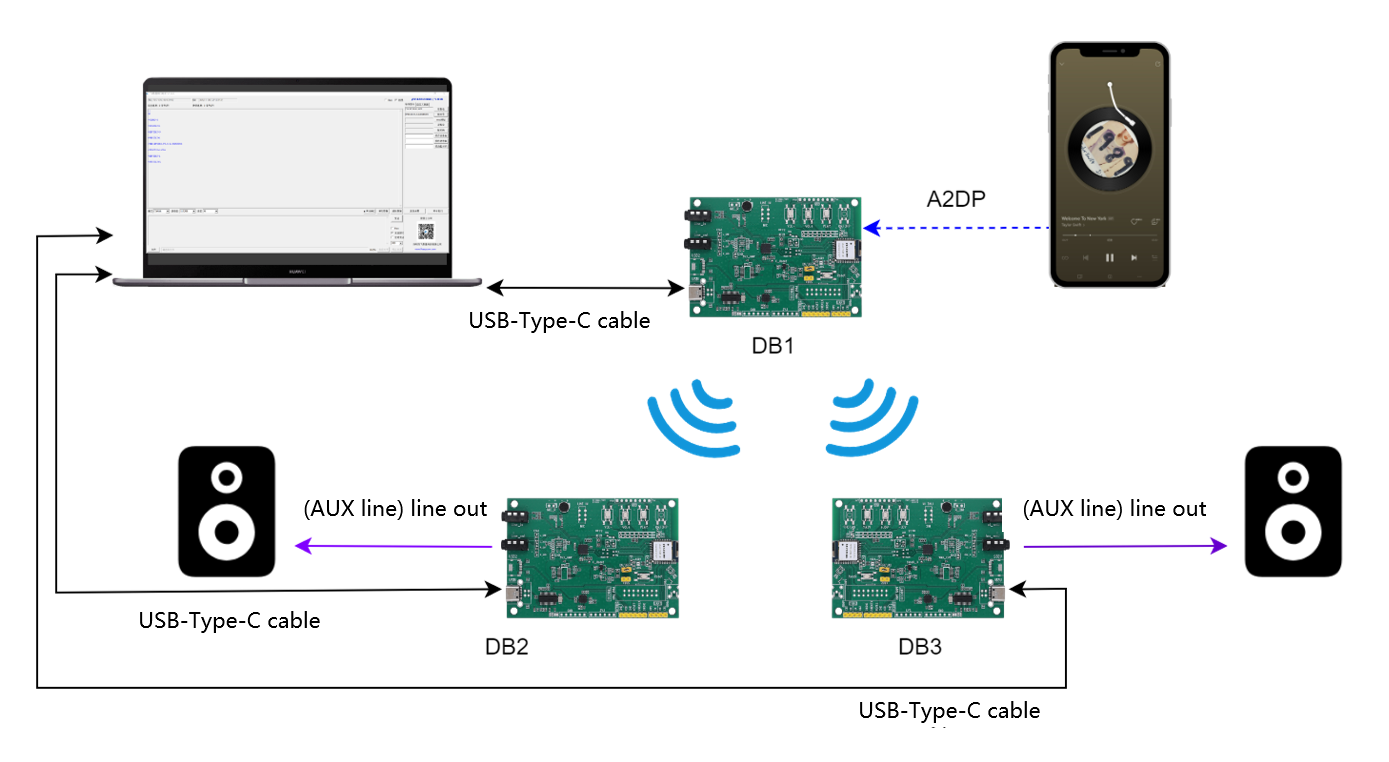
Application Demo
EVB DB1(FSC-DB215-BT631D):Connect via a Type-C cable to a PC. Upon successful connection, the PC will automatically recognize the serial port device and generate a virtual COMx.
EVB DB1(FSC-DB215-BT631D):Set the Profile of the Bluetooth module (FSC-BT631D) and enable HFP-HF, A2DP-Sink, and BIS Gateway. The specific AT command operations and responses are as follows:
>>AT+PROFILE=9385            //Enable HFP-HF,A2DP-Sink,and BIS Gateway profiles
<<
OK

+BISSTAT=1
+DEVSTAT=0
+BISSTAT=5
+PWRSTAT=1
+SPPSTAT=1
+VER=BT631D,V3.0.9,20250306        //Example, please refer to the actual firmware version.
+PROFILE=9385
+A2DPMUTED=0
+A2DPSTAT=1
+ABSVOL=0
+AVRCPSTAT=1
+HFPSTAT=1
+PBSTAT=1
+DEVSTAT=1
+DEVSTAT=3
EVB DB1(FSC-DB215-BT631D):The development board supports configuration into three audio input modes (USB, lineIn, and A2DP) via AT commands. Here we demonstrate the A2DP audio input mode, the AT command configuration operations as follows:
>>AT+AUXCFG=2    //Enable A2DP audio input mode
<<
+DEVSTAT=3
OK

Note: Parameter 2 is only valid when the A2DP Sink Profile is enabled.
NOTE:The default program of FSC-BT631D is Classic Audio Sink + LE Audio Gateway simultaneous support mode, that is, the audio stream flows from A2DP Source (Classic Audio Source, such as a mobile phone) to A2DP Sink (Classic Audio Sink), and then is broadcast via LE Audio.
EVB DB2(FSC-DB215-BT631D) :Connect via a Type-C cable to a PC. Upon successful connection, the PC will automatically recognize the serial port device and generate a virtual COMx. Connect the LineOut component on the development board to an external audio device (such as wired headphones or speakers) using an AUX cable at the same time.
EVB DB2(FSC-DB215-BT631D):Set the Profile of the corresponding Bluetooth module FSC-BT631D and enable BIS Headset. The AT command operations and responses are as follows:
>>AT+PROFILE=16384            //Enable BIS Headset Profile
<<
OK

+BISSTAT=1
+DEVSTAT=0
+PWRSTAT=1
+VER=BT631D,V3.0.9,20250306
+PROFILE=16384
+DEVSTAT=1
+DEVSTAT=3
EVB DB2(FSC-DB215-BT631D):Establish BIS audio connection with the specified BIS Gateway device. The AT command operations and responses are as follows:
 >>AT+SCAN=4        //Scan for nearby BIS/CIS device broadcast source
 <<+DEVSTAT=67
 OK
 +SCAN=0,-39,5,DE0D3000187D,FSC-BT631D-BIS-187E,885
 ...
 ...
 +SCAN=E            //Scan Completed
 +DEVSTAT=3

 >>AT+BISCONN=FSC-BT631D-BIS-187E     //Initiate LE audio BIS connection with specified device by BIS Gateway name.
 <<+BISSTAT=2                         //Establishing BIS connection
 OK
 +DEVSTAT=65
 +BISSTAT=5                          //Established BIS connection and receiving BIS data
Mobile Phone Side:On the mobile phone, scan for the classic Bluetooth of the development board DB1 (FSC-DB215-BT631D) and establish an A2DP audio connection. The operation diagram is as follows:
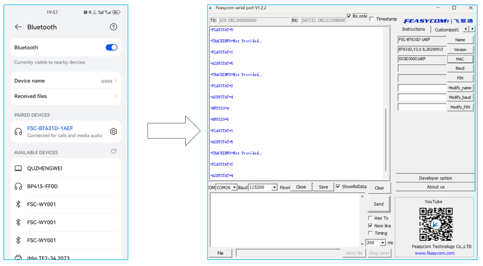
EVB DB1(FSC-DB215-BT631D):After the Bluetooth connection between the mobile phone and the development board’s A2DP audio link is successfully established, the development board’s serial port response events are as follows:
<<
...
...
+HFPSTAT=3
+HFPDEV=2C0000000000,hmsNext
+DEVSTAT=1
+PLAYSTAT=2
+A2DPSTAT=3                  //A2DP Connected
+A2DPDEV=2C0000000000,hmsNext
+AVRCPSTAT=2
+AVRCPSTAT=3
+TRACKINFO=Welcome To New York,Taylor Swift,1989 (Deluxe)
Mobile Phone: Open the music player and play music.
EVB DB1(FSC-DB215-BT631D):Receive the A2DP audio stream from the mobile phone side (audio stream data output via serial port) and simultaneously send the BIS broadcast audio stream. The diagrams and serial port events are as follows:
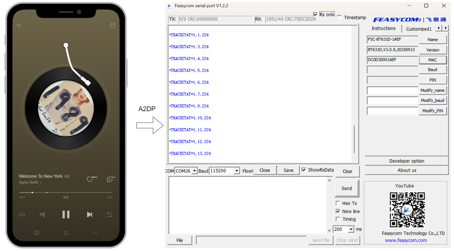
<<
+A2DPSTAT=5
+PLAYSTAT=1
+TRACKINFO=Welcome To New York,Taylor Swift,1989 (Deluxe)
+TRACKSTAT=1,1,212
+TRACKSTAT=1,2,212
+TRACKSTAT=1,3,212
...
...
EVB DB2(FSC-DB215-BT631D):Receive the BIS broadcast audio stream from the DB1 side (BIS Gateway), and simultaneously output the audio stream to the external audio device through the development board’s LineOut component—meaning the external audio device can synchronously play the audio stream from the mobile phone side.
Expand more devices to receive BIS broadcast audio:The current development board supports an unlimited number of BIS broadcast audio receiving devices (BIS headsets), such as DB3. Simply repeat Steps 4, 5, and 6 for configuration.
Contact Information
Shenzhen Feasycom Co.,Ltd.
Address : Rm 508, Building, Fenghuang Zhigu, NO.50, Tiezai Road, Xixiang, Baoan Dist, Shenzhen, 518100, China.
Telephone : 86-755-23062695
Support : support@feasycom.com
Sales Service : sales@feasycom.com
Home Page : www.feasycom.com
Support Forum : forum.feasycom.com