FSC-DB105 User Guide
[Version: 1.0] [中文版]
This guide introduces how to use the FSC-DB105 and provides further information about this development board.
Overview
FSC-DB105 is a rapid evaluation board specifically designed for Feasycom’s Bluetooth Dual-Mode (BLE & SPP) + Wi-Fi SOC module data transmission applications. With this evaluation board, customers can easily and efficiently run tests for their projects. Coupled with the user guide, customers can test all functionalities built into the default firmware using AT commands.
|
|---|
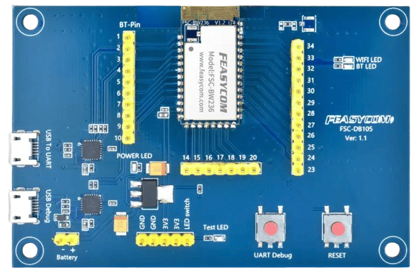
FSC-DB105 with FSC-BW236 module |
Scope of Application
Applies to :
FSC-BW236
FSC-BW246
FSC-BW256B
…
and other Feasycom Bluetooth + Wi-Fi SOC Modules for application development.
Functional Components
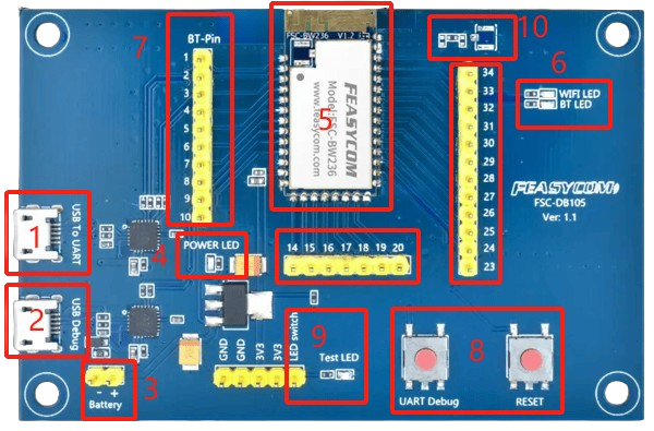
Description by labeled number
No. |
Component |
Description |
|---|---|---|
1 |
USB To UART |
USB to UART (Micro-B USB): USB power supply interface, data communication interface. Used to send AT commands and exchange data with the module. |
2 |
USB Debug |
USB to UART (Micro-B USB): Debug log data output interface. |
3 |
Battery |
Battery power interface (optional, disconnected by default). |
4 |
POWER LED |
Steadily on (red) after power-up, indicates normal power supply. |
5 |
Module SMD Area |
Sample image shows a soldered Feasycom FSC-BW236 module. |
6 |
WiFi LED |
WiFi LED: Wi-Fi status indicator, steadily on when connected to router, off when disconnected. |
7 |
BT-Pin |
Module pin extension header interface, numbers correspond to module pin numbers. |
8 |
RESET Control Button |
1. Firmware Download Mode Control: Press and hold the UART Debug button, then press and release the RESET button once, finally release the UART Debug button to enter firmware download mode. |
9 |
Test LED |
Test LED light, lights up when LED switch receives a high level. |
10 |
External Antenna IPEX |
(Reserved) π-shaped circuit and IPEX area for external antenna. |
What You Need
Required Hardware
1 x FSC-DB105-BW236 Development KIT: FSC-DB105 board pre-integrated with a Feasycom FSC-BW236 (optional)
1 x USB to Micro-B Cable
1 x PC (Windows / Mac)
1 x Mobile Phone (Android / iOS)
Software and Setup
Serial Driver: CP210x_Universal_Driver.zip for Windows PC, generally plug-and-play, install this driver if the PC fails to recognize the device in specific environments.
Feasycom Serial Port Tool : A serial communication analysis tool based on Windows PC.
FeasyBlue :Feasycom APP & SDK resource supporting Android and iOS platforms, which enables functions such as Bluetooth BLE & SPP data communication debugging, Feasycom module firmware version reading, firmware OTA upgrade,parameter configuration, etc.
Communication Interface: UART
Serial Configuration: 115200/8/N/1 (Feasycom general firmware default)
Hardware Access
Power-on Options
The development board can be powered by any one of the following methods:
Micro-B USB power supply (default)
3V3 / GND pin power supply
Note: The above power supply modes must not be connected simultaneously, as this may damage the development board and/or the power source.
Hardware Access Note
Before powering on, ensure the development board is intact and all components are secure without looseness or shorts.
Connect the development board to the PC using the USB to Micro-B cable.
After powering on, the LED lights up steadily, indicating the board is powered normally and ready for debugging.
Quick Start
Hardware Access and Start
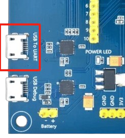
Connect the FSC-DB105-BW236 development board’s USB To UART port (Component 1) to the PC using the USB to Micro-B cable. The indicator LED lights up steadily, indicating the FSC-BW236 module has started successfully. See sample image below:
Serial Port Recognition
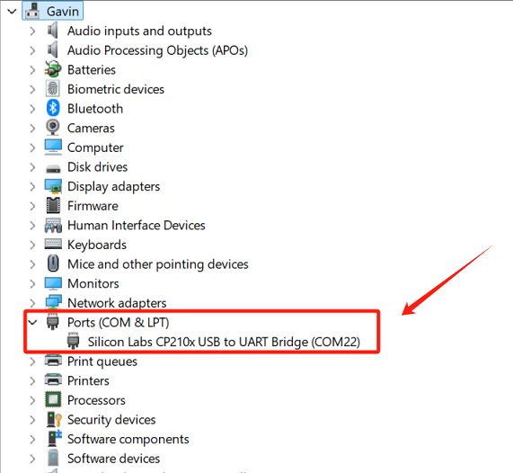
After successful hardware connection and startup of the FSC-DB105-BW236, it is plug-and-play. The PC will recognize the USB serial device and create a virtual COMx port. Example below:
AT - Serial Communication Test
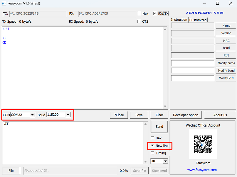
Open Feasycom Serial Port Tool on the PC. Automatically obtain or manually select the corresponding COMx port, set the matching baud rate (e.g., 115200), check the Send New Line option, and send the serial communication test command AT. If the response is OK, the serial communication test is successful. Command format and example are shown in the image below:
Command |
AT\r\n |
|---|---|
Response |
\r\nOK\r\n |
Description |
Test the UART communication between HOST and Module after power on, baudrate changed, etc. |
Example:
send:     >>AT\r\n
response: <<\r\nOK\r\n   //Successfully connected.
Application Examples
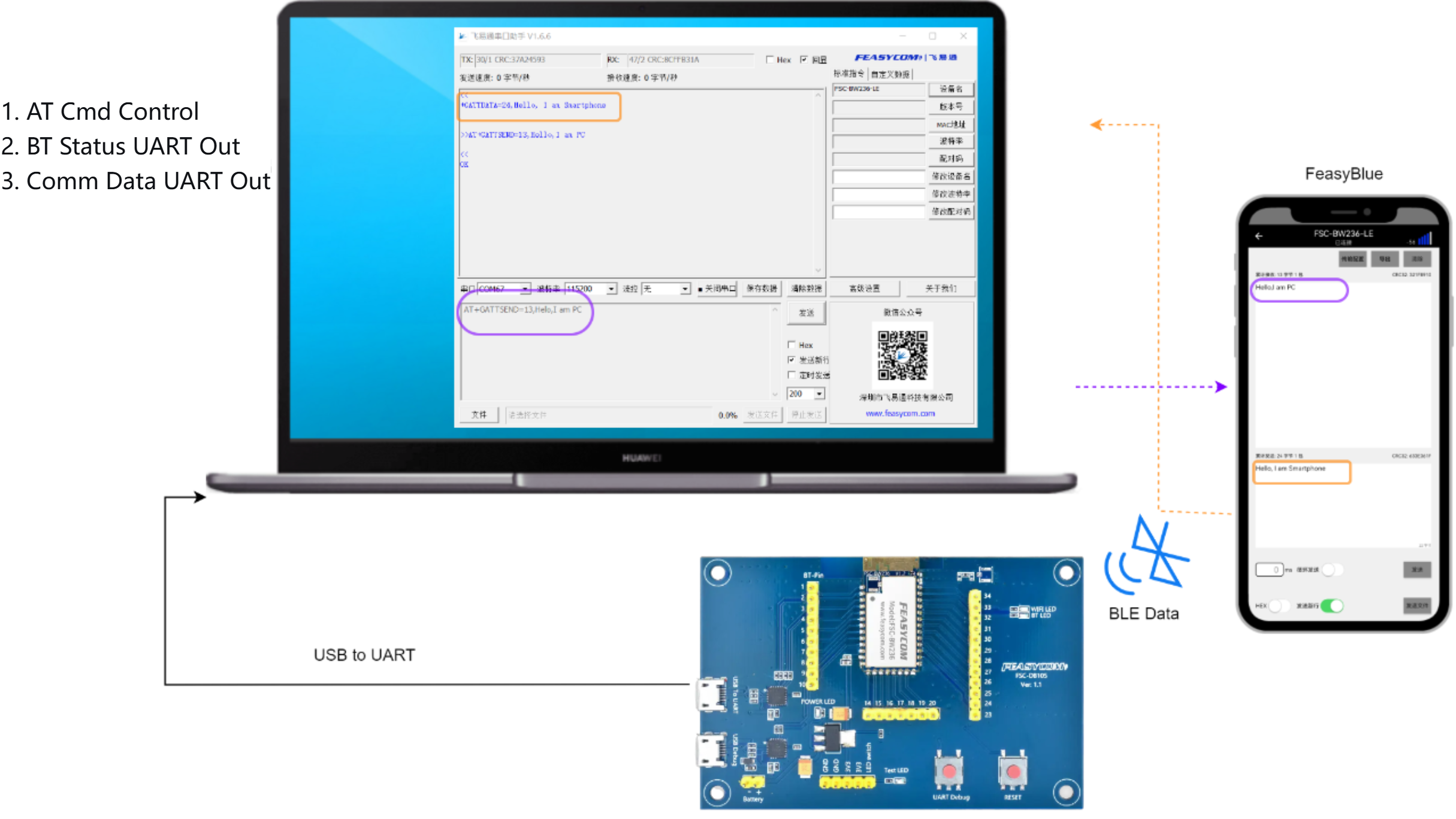
Bluetooth Application Example
FSC-BW236 only supports BLE and does not support SPP.
FSC-BW246 and FSC-BW256B can support BLE and SPP.
Application Diagram
The application block diagram below is also suitable for Bluetooth BLE and SPP data transmission debugging with FeasyBlue:
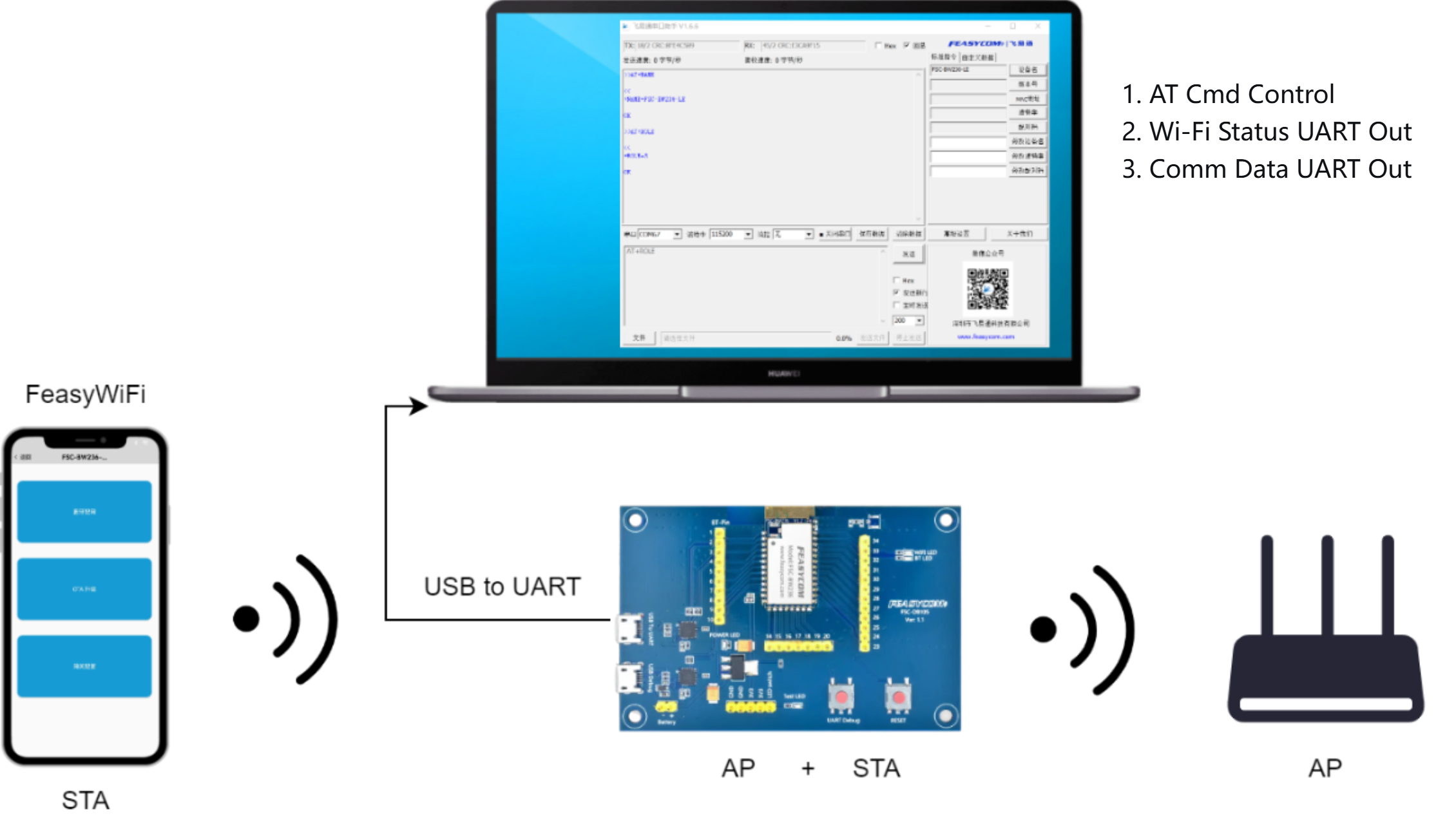
Wi-Fi Application Example
Application Diagram : STA+AP
Contact Information
Shenzhen Feasycom Co.,Ltd.
Address : Rm 508, Building, Fenghuang Zhigu, NO.50, Tiezai Road, Xixiang, Baoan Dist, Shenzhen, 518100, China.
Telephone : 86-755-23062695
Support : support@feasycom.com
Sales Service : sales@feasycom.com
Home Page : www.feasycom.com
Support Forum : forum.feasycom.com